OJT Records Monitoring System ER Diagram
This article will describe the step by step procedure on how to construct the entity relationship diagram or ERD of the project entitled OJT Records Monitoring System.
OJT Records Monitoring System Description
The system will serve as a repository for the records of students who participate in on-the-job training in an organization. The system will allow the organization, and specifically the OJT coordinator, to keep track of the progress of the trainee as well as the tasks done by him or her during the program. In addition, the system will store the trainee’s records electronically so that they can be retrieved at any time. Using the system will be a dependable and cost-effective experience.
The following are some of the benefits of the OJT Records Monitoring System:
- Automated Monitoring- The system will allow the OJT coordinators to quickly track the records of the students who are participating in the program.
- It is a database system that makes records electronic, safe, accurate, and dependable while also being quick and easy to access and retrieve.
- Report Generation — During the OJT term, the system will automatically generate reports on the status of the students.
for more information about the system, you may visit the link below:
OJT Records Monitoring System ERD
This is the first phase of the development of the OJT Records Monitoring System, which will eventually be used as the basis for the production of the actual database that will be used by the system.
We will develop an entity relationship diagram for the OJT Records Monitoring System and describe the steps involved in creating the diagram.
Let us begin with the symbols that are used in the ER Diagram.
The rectangle shape represents the entity being represented. Later on, we will use this entity to create a database table for our OJT Records Monitoring System.
The oval form represents the attribute being represented. The OJT Records Monitoring System will have columns or fields for each table, and this will be the case.
The shape of a diamond shows how a relationship works. This will determine how things connect with each other. If you use a primary key to foreign keys relationship, you can often do this.
We will follow the 3 basic rules in creating the ER Diagram.
- Identify all the entities.
- Identify the relationship between entities and
- Add meaningful attributes to our entities.
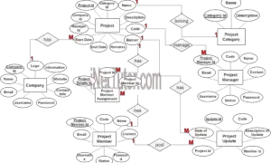
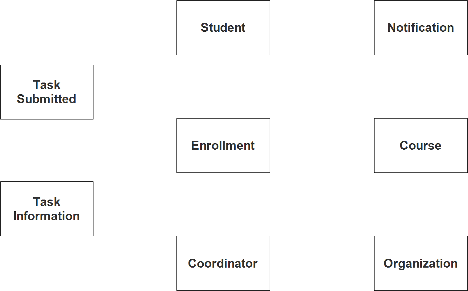
Step 1. In the OJT Records Monitoring System we have the following entities:
- Student
- Course
- Enrollment
- Organization
- Coordinator
- Task Information
- Task Submitted
In line with our design, the OJT Records Monitoring System is made up of seven components. When we design and develop the OJT Records Monitoring System database schema, the components that make up these parts will be the segments of our database tables.
To illustrate the system as a whole, we’ll design a rectangle with the entities of the OJT Records Monitoring System arranged inside it. Following is a diagram depicting the entities that have been identified as functioning under the scope of the OJT Records Monitoring System.
Step 2. After we have specified our entities, it is time now to connect or establish a relationship among the entities.
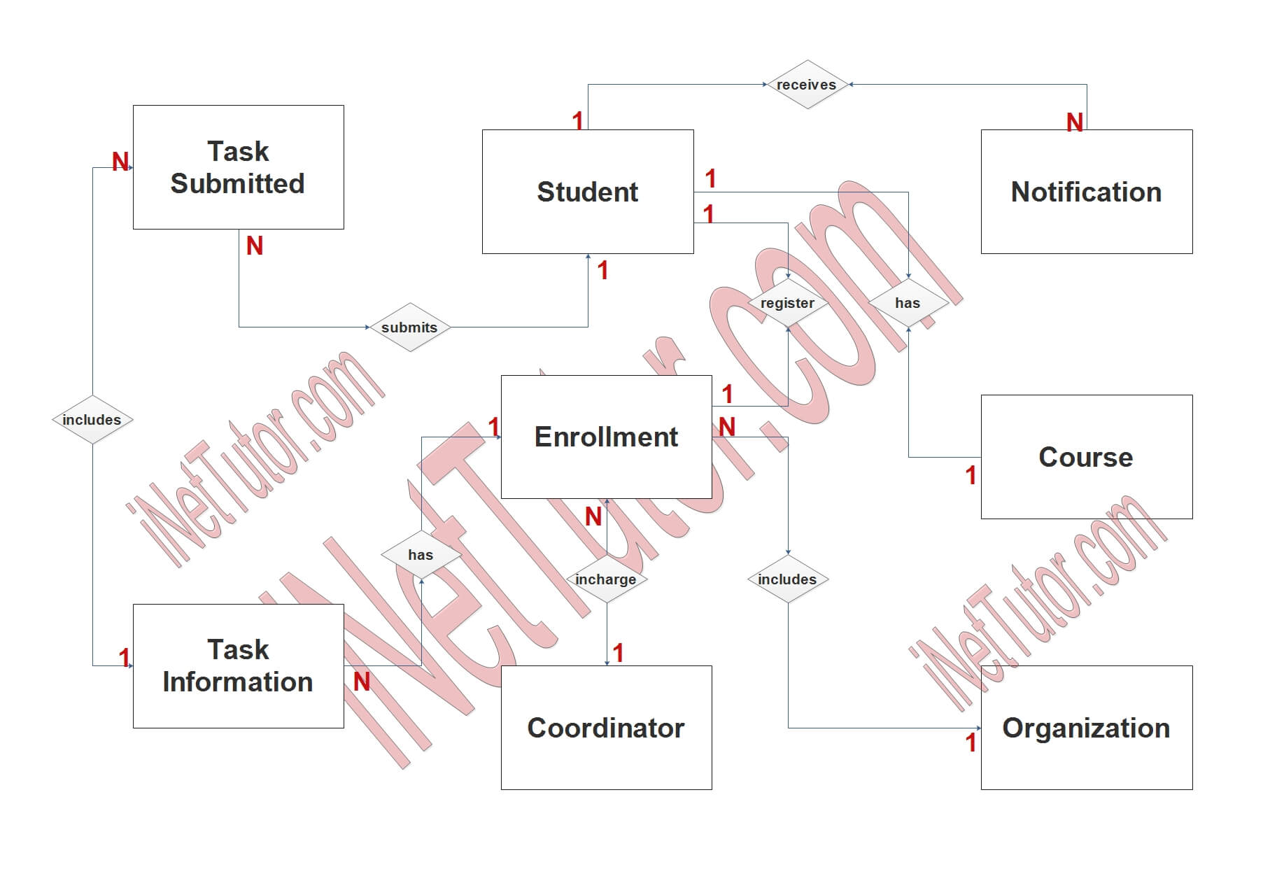
- The student can only be a part of one class or one course (1 to 1 relationship).
- Student can receive notifications from their coordinator (1 to N relationship).
- Student can only enroll or register once in an OJT program (1 to 1 relationship).
- Student will submit requirements based on the deliverables set by their coordinator (1 to N relationship).
- Task Information is included in the submissions of the students (1 to N relationship).
- Enrollment record is attached to the task information to archive the list of requirements per school year (1 to N relationship).
- An organization can handle multiple trainees. It will depend on the manpower they need (1 to N relationship).
- An OJT program is also a subject requirement which means that it has also a class or section. Based on that description, the coordinator can handle multiple class sections that will take the OJT program (1 to N relationship).
Step 3. The last part of the ERD process is to add attributes to our entities.
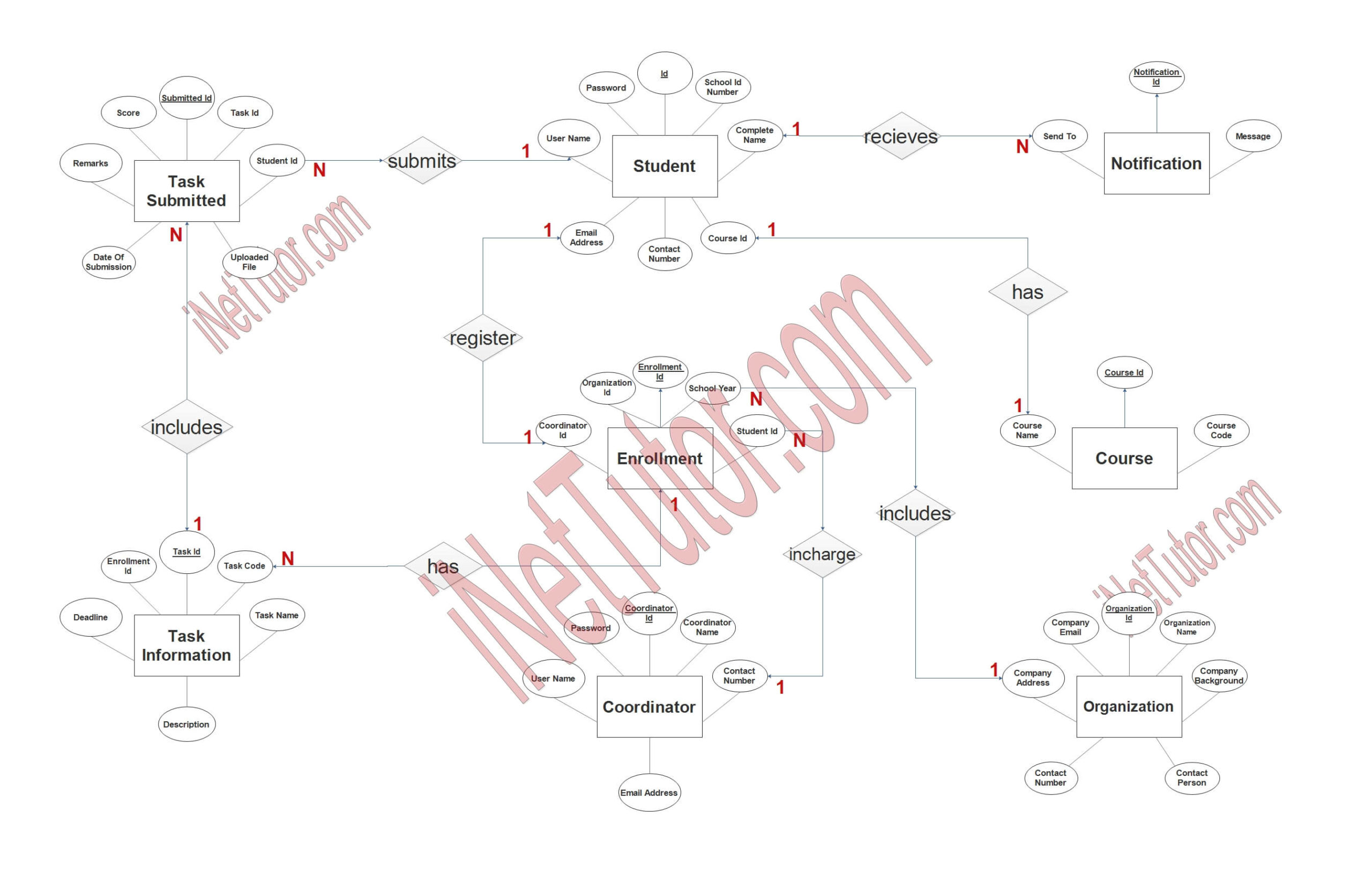
Student
- Student ID – primary key represented with underline
- School ID number
- Complete name
- Course ID – foreign key
- Contact number
- Email address
- Username
- Password
Course
- Course ID – primary key represented with underline
- Course code
- Course name
Enrollment
- Enrolment ID – primary key represented with underline
- School year
- Student ID – foreign key
- Coordinator ID – foreign key
- Organization ID – foreign key
Organization
- Organization – primary key represented with underline
- Organization name
- Company background
- Contact person
- Contact number
- Company address
- Company email
Coordinator
- Coordinator ID – primary key represented with underline
- Coordinator name
- Contact number
- Email address
- Username
- Password
Task Information
- Task ID – primary key represented with underline
- Task code
- Task name
- Description
- Deadline
- Enrolment ID – foreign key
Task Submitted
- Submitted – primary key represented with underline
- Task ID
- Student ID
- Uploaded File
- Date of submission
- Remarks
- Score
Notification
- Notif ID – primary key represented with underline
- Message
- Send to – foreign key
User
- User ID – primary key represented with underline
- Complete name
- Username
- Password
Summary
The ER Diagram will serve as a guide and a source of reference for the developers while they create the actual database for the project. ER Diagram If you have gained any knowledge from our post on how to build and construct an ER Diagram for OJT Records Monitoring System, please feel free to pass it on to other people.
In addition, we will provide a Powerpoint/Video Presentation for the entire ER Diagram contents. Please visit and subscribe to our YouTube Channel in order to access the contents of the ER Diagram Videos.
You may visit our Facebook page for more information, inquiries, and comments. Please subscribe also to our YouTube Channel to receive free capstone projects resources and computer programming tutorials.
Hire our team to do the project.
Related Links and Articles:
OJT Records Monitoring System 100% Free Template
OJT Timesheet Monitoring System using QR Code
OJT Records Monitoring System Chapter 1