Medical Record and Billing System ER Diagram
The capstone project entitled Medical Record and Billing System is a system that is intended to run on a local area network but the researchers designed and developed in a web based using PHP, MySQL and Bootstrap. Projects developed in PHP can be deployed to both local setup and online servers. The core features of the system includes the medical records of the patient integrated with the billing transaction
You may visit and read the articles posted in relation to Medical Record and Billing System
- Abstract of Medical Record and Billing System
- Medical Record System in PHP and MySQL User Interface
- LAN-based Electronic Medical Record System Thesis Documentation
- Patient Medical Records System Review of Related Literature
- Medical Record System Database Design
- Computerized Clinic and Medical Records Management System Free Download Source code
- Medical and Dental Record System User Interface and Features
- Medical and Laboratory Records and Archiving System Capstone Project
This article will discuss the step by step process on how to prepare the entity relationship diagram or ERD of the project entitled Medical Record and Billing System.
The first step in the development of the Medical Record and Billing System is to prepare the ER diagram that will serve as the basis later on in the creation of the actual database.
We will create and explain the process of making the entity relationship diagram of Medical Record and Billing System.
Let’s start from the symbols used in the ER Diagram.
Entity is represented by the rectangle shape. The entity will be our database table of Medical Record and Billing System later on.
Attribute is represented by the oval shape. This will be the columns or fields of each table in the Medical Record and Billing System.
Relationship is represented by diamond shape. This will determine the relationships among entities. This is usually in a form of primary key to foreign key connection.
We will follow the 3 basic rules in creating the ER Diagram.
- Identify all the entities.
- Identify the relationship between entities and
- Add meaningful attributes to our entities.
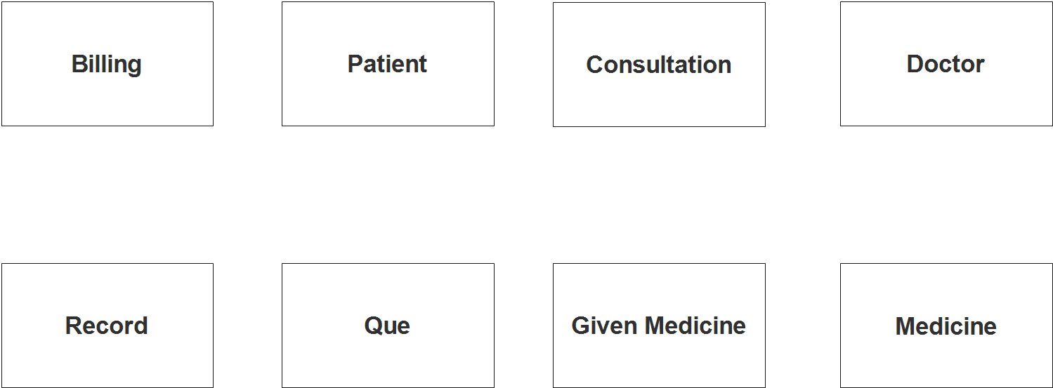
Step 1. In the Medical Record and Billing System we have the following entities
- Patient
- Lab Record
- Doctor
- Consultation
- Medicine
- Given Medicine
- Que
- Billing
Our design of Medical Record and Billing System consists of 8 entities; the specified entities will be our database tables in the design and implementation of Medical Record Billing database schema.
We will now draw the entities of the Medical Record and Billing System specified above and it will be represented by a rectangle shape. The image below is the entities identified in the scope of the Medical Record and Billing System.
Step 2. After we have specified our entities, it is time now to connect or establish a relationship among the entities.
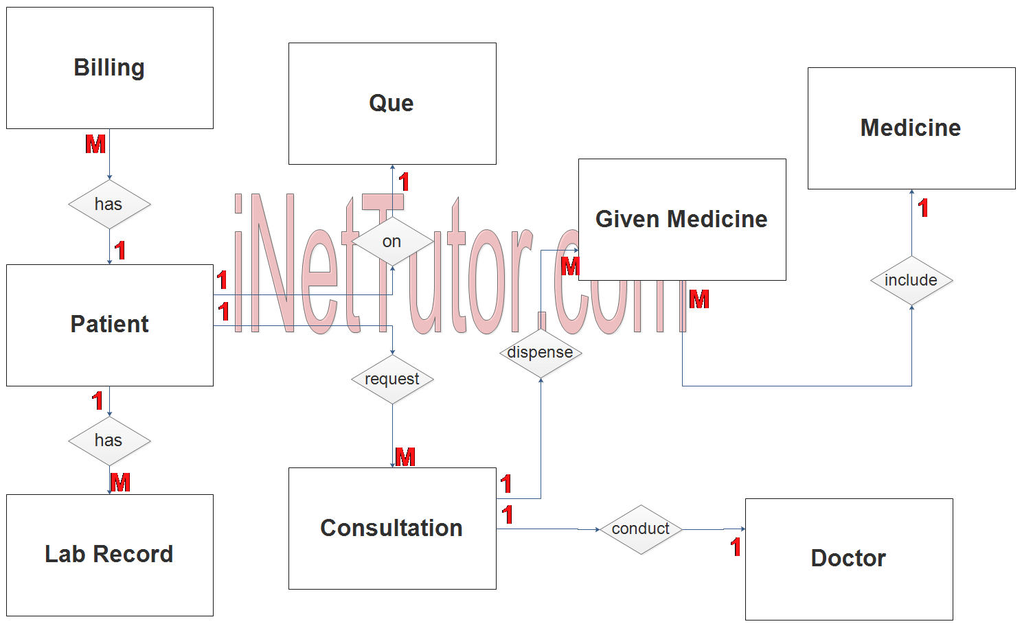
- The patient has lab records and consultation history for future references (1 to many relationship).
- Every transaction from consultation or check-up and laboratory requests has a billing statement (1 to many relationship).
- Patient can request for a consultation (1 to many relationship). This relationship can also be 1 to 1 relationship since the patient can only request a check-up one at a time. In this case, it refers to the number of records stored in the system.
- For every consultation or checkup, there is a physician assigned to the patient (1 to 1 relationship).
- Medicine will be dispense for every consultation or check-up of the patient (1 to many relationship).
Step 3. The last part of the ERD process is to add attributes to our entities.
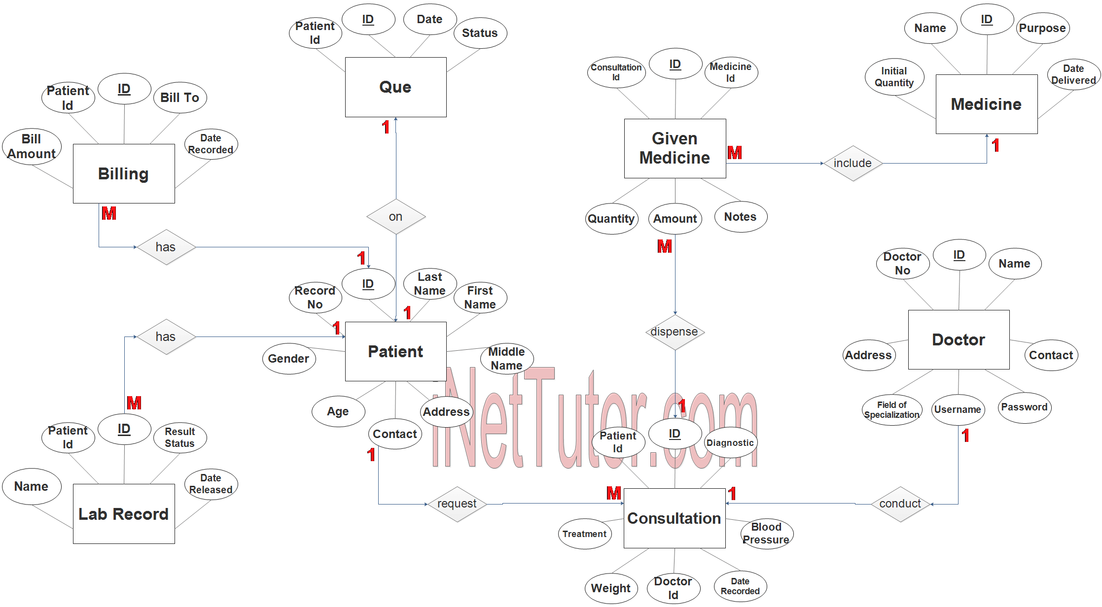
Patient Entity has the following attributes:
- ID – primary key represented with underline
- Record No
- Last name
- First name
- Middle name
- Gender
- Age
- Contact
- Address
Lab Record Entity has the following attributes:
- ID – primary key represented with underline
- Patient ID – foreign key
- Lab Record Name
- Result Status
- Date Released
Doctor Entity has the following attributes:
- ID – primary key represented with underline
- Doctor No
- Name
- Address
- Field of specialization
- Contact
- Username
- Password
Consultation Entity has the following attributes:
- ID – primary key represented with underline
- Patient ID – foreign key
- Diagnostic
- Treatment
- Weight
- Blood Pressure
- Doctor ID – foreign key
- Date Recorded
Medicine Entity has the following attributes:
- ID – primary key represented with underline
- Name
- Initial Quantity
- Purpose
- Date Delivered
Given Medicine Entity has the following attributes:
- ID – primary key represented with underline
- Consultation ID –foreign key
- Medicine ID – foreign key
- Quantity
- Amount
- Notes
Que Entity has the following attributes:
- ID – primary key represented with underline
- Patient ID – foreign key
- Date
- Status
Billing Entity has the following attributes:
- ID – primary key represented with underline
- Patient ID – foreign key
- Bill To
- Bill Amount
- Date Recorded
Note: all attributes with underline represents the primary key of the entity or table.
The next step is to convert the plan designed on ER Diagram into the actual database, please search for the Medical Record and Billing System article which was already posted.
Contact us on our facebook page for the softcopy of the Medical Record and Billing System.
You may visit our facebook page for more information, inquiries and comments.
Hire our team to do the project.