Cemetery Mapping Information System ER Diagram
This article will walk you through the process of creating the entity relationship diagram (ERD) for the project Cemetery Mapping Information System.
About the System
Table of Contents
The researcher of the system entitled “Cemetery Mapping Information System” aimed to provide a platform for the user to quickly locate and less effort on finding their relative graves and a platform for the personnel to access, update and maintain the data in an efficient manner. With this system, the user will not be worry about locating the grave of their deceased loved ones.
A Cemetery Mapping Information System is a computer-based system that is used to track and manage information about graves, burial plots, and other cemetery-related data. The system typically includes a database with records for each grave and burial plot, as well as maps or other visual representations of the cemetery layout. The system may also include information about the deceased, such as names, dates of birth and death, and other relevant details.
The primary purpose of a Cemetery Mapping Information System is to provide a centralized, easy-to-use resource for managing and accessing cemetery information. It allows cemetery administrators and staff to easily locate graves and burial plots, track the availability of graves and plots, and access information about the deceased interred in the cemetery. It can also be used by cemetery visitors to locate graves and plots, or to search for information about specific individuals.
ER Diagram
We will develop and describe the entity relationship diagram of the Cemetery Mapping Information System.
Let us begin with the symbols utilized in the ER Diagram.
The rectangle form represents the entity. Later on, the entity will be our database table of the Cemetery Mapping Information System.
The oval shape represents attribute. The columns or fields of each table in the Cemetery Mapping Information System will be listed here.
The diamond form represents a relationship. This will establish the associations between entities. This is often done through a primary key to foreign key relationship.
We will follow the 3 basic rules in creating the ER Diagram.
- Identify all the entities.
- Identify the relationship between entities and
- Add meaningful attributes to our entities.
Step 1. Identify the Entities
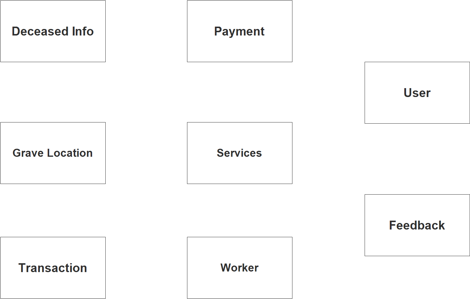
In the Cemetery Mapping Information System we have the following entities:
- Deceased info
- Grave location
- Transaction
- Payment
- Services
- Worker
- User
- Feedback
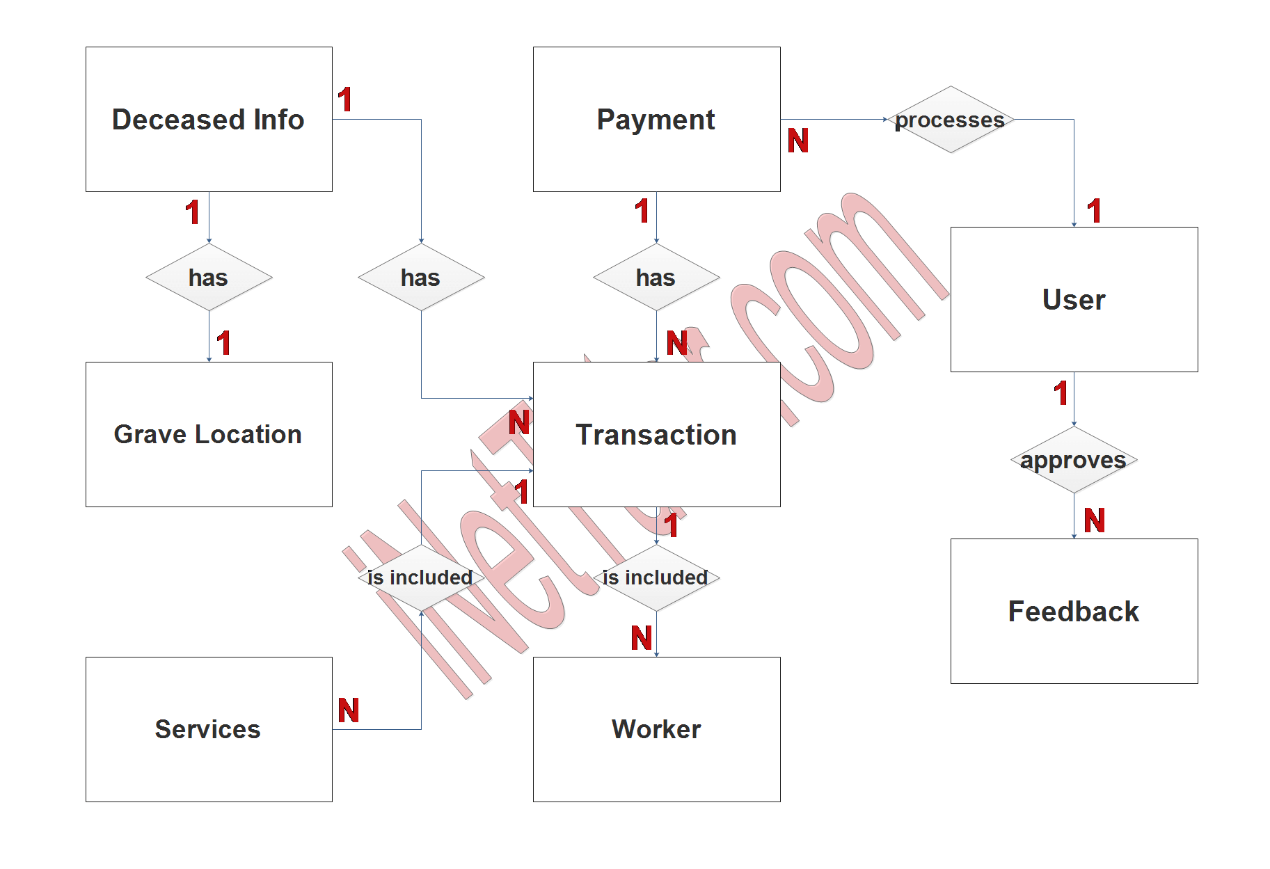
We will now draw the entities of the Cemetery Mapping Information System specified above and it will be represented by a rectangle shape. The image below is the entities identified in the scope of the Cemetry Mapping Information System.
Step 2. Establish Relationships
After we have specified our entities, it is time now to connect or establish a relationship among the entities.
- grave_id has tbl_grave_location.grave_id (1:1)
tbl_grave_location.grave_id means that each deceased person is buried in one, and only one, grave. Similarly, each grave can only contain one deceased person. The grave_id field in both tables is used to link the two tables and establish this one-to-one relationship.
- deceased_id has tbl_transaction. deceased_info_id (1:N)
A one-to-many relationship between tbl_deceased_info.deceased_id and tbl_transaction.deceased_info_id means that each deceased person can have zero, one, or many transactions associated with them. For example, a deceased person might have a transaction for purchasing a grave, another transaction for purchasing a headstone, and another transaction for arranging a funeral service. On the other hand, each transaction is only associated with one deceased person. The deceased_info_id field in the tbl_transaction table is used to link the two tables and establish this one-to-many relationship.
- transaction_id has tbl_payment.transaction_id (1:N)
A many-to-one relationship between tbl_transaction.transaction_id and tbl_payment.transaction_id means that each transaction can have zero, one, or many payments associated with it. This might occur if a transaction is paid in installments, or if a transaction requires multiple forms of payment (e.g. cash and credit). On the other hand, each payment is only associated with one transaction. The transaction_id field in the tbl_payment table is used to link the two tables and establish this many-to-one relationship.
- services_id is included tbl_transaction.service_id (1:N)
A many-to-one relationship between tbl_services.services_id and tbl_transaction.service_id means that each service can be included in zero, one, or many transactions. This might occur if a service is purchased multiple times, or if a transaction includes multiple services. On the other hand, each transaction is only associated with one service. The service_id field in the tbl_transaction table is used to link the two tables and establish this many-to-one relationship.
- worker_id is included tbl_transaction.worker_id (1:N)
A many-to-one relationship between tbl_worker.worker_id and tbl_transaction.worker_id means that each worker can be included in zero, one, or many transactions. This might occur if a worker performs multiple services for different transactions, or if a transaction includes multiple workers. On the other hand, each transaction is only associated with one worker. The worker_id field in the tbl_transaction table is used to link the two tables and establish this many-to-one relationship.
- user_id processes tbl_payment.user_id (1:N)
A one-to-many relationship between tbl_user.user_id and tbl_payment.user_id means that each user can process zero, one, or many payments. This might occur if a user processes multiple payments for different transactions, or if a payment is split among multiple users. On the other hand, each payment is only processed by one user. The user_id field in the tbl_payment table is used to link the two tables and establish this one-to-many relationship.
- user_id approves tbl_feedback.user_id (1:N)
A one-to-many relationship between tbl_user.user_id and tbl_feedback.user_id means that each user can approve zero, one, or many pieces of feedback. This might occur if a user is responsible for reviewing and approving feedback from multiple customers, or if a piece of feedback is approved by multiple users. On the other hand, each piece of feedback is only approved by one user. The user_id field in the tbl_feedback table is used to link the two tables and establish this one-to-many relationship.
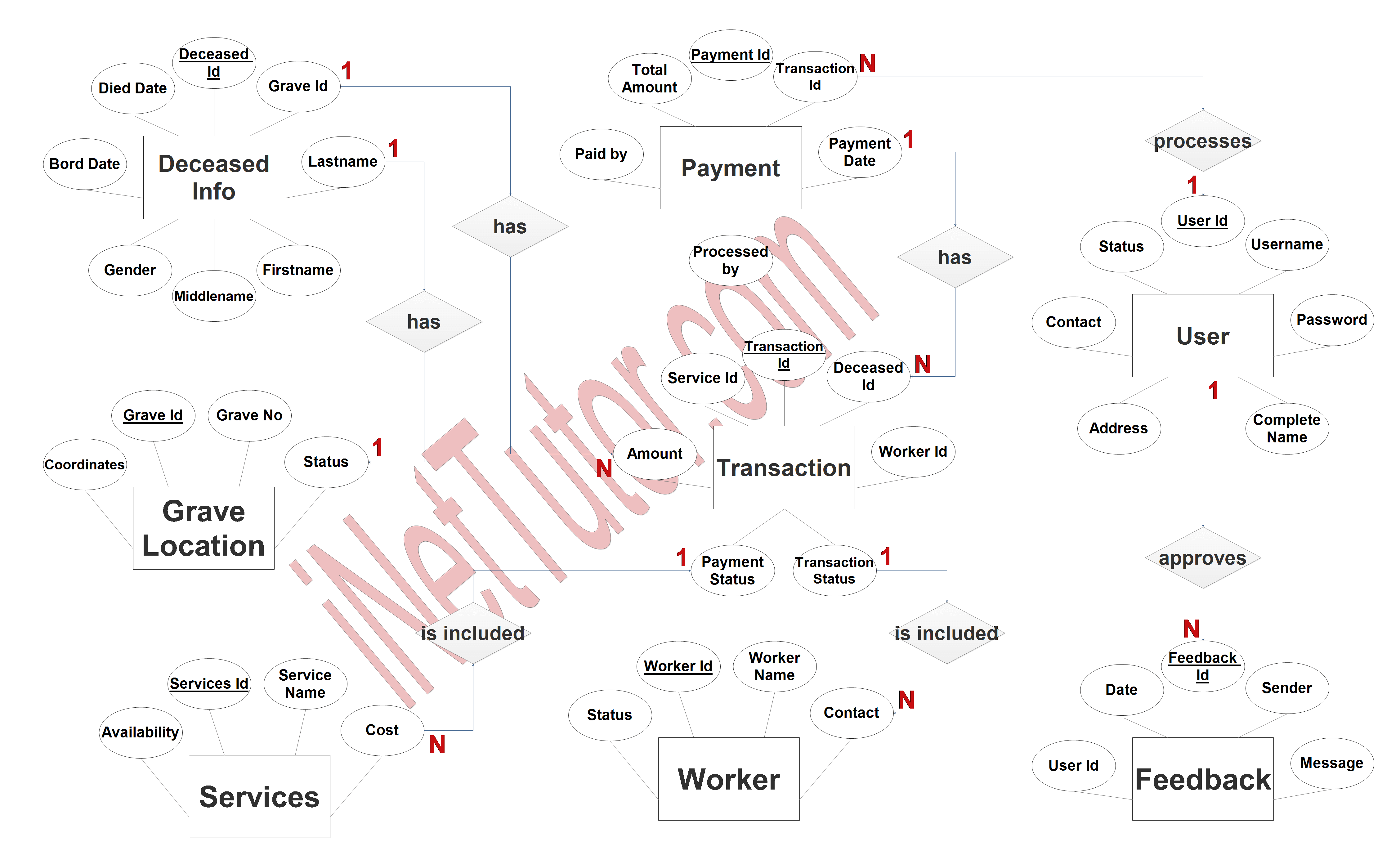
Step 3. Add Meaningful Attributes
The last part of the ERD process is to add attributes to our entities.
Deceased_info entity has the following attributes:
- Deceased ID – primary key
- Grave ID – foreign key
- Last name
- First name
- Middle name
- Gender
- Born date
- Died date
Grave_location entity has the following attributes:
- Grave ID – primary key
- Grave no
- Status
- Coordinates
Transaction entity has the following attributes:
- Transaction ID – primary key
- Deceased info ID – foreign key
- Service ID – foreign key
- Amount
- Worker ID – foreign key
- Payment status
- Transaction status
Payment entity has the following attributes:
- Payment id – primary key
- Transaction id – foreign key
- Total amount
- Paid by
- Payment date
- Processed by
Services entity has the following attributes:
- Services ID – primary key
- Service name
- Cost
- Availability
Worker entity has the following attributes:
- Worker ID – primary key
- Worker name
- Contact
- Status
User entity has the following attributes:
- User ID – primary key
- Username
- Password
- Complete name
- Contact
- Address
- Status
Feedback entity has the following attributes:
- Feedback ID – primary key
- Sender
- Message
- Date
- User id – foreign key
Summary
A Cemetery Mapping Information System (CMIS) is a database-driven system that is used to track and manage information about graves, burial plots, and other cemetery-related data. One way to understand the structure and relationships within a CMIS is to create an Entity Relationship (ER) diagram.
An ER diagram is a graphical representation of the entities and relationships within a database. In the context of a CMIS, the entities might include graves, burial plots, deceased individuals, transactions, and users. The relationships between these entities can be one-to-one, one-to-many, or many-to-one.
By creating an ER diagram for a CMIS, we can gain a better understanding of the structure and relationships within the system, and how the various entities and data points are connected. This can be useful for database design, data analysis, and other purposes.
Readers are also interested in:
Cemetery Mapping Database Project
Online Reservation of Cemetery with Map Navigation
Cemetery Mapping Information System
You may visit our Facebook page for more information, inquiries, and comments. Please subscribe also to our YouTube Channel to receive free capstone projects resources and computer programming tutorials.
Hire our team to do the project.