Hospital Resources and Room Utilization ER Diagram
This article will walk you through the process of creating an entity relationship diagram, often known as an ERD, for the project entitled Hospital Resources and Room Utilization.
Hospital Resources and Room Utilization Description
Resources and room usage should be tracked by department, date, and time using the hospital database system. Data on resources, such as the category, department, and quantity of resources, should be able to be stored by the system. Additionally, the system should be able to retain information on room usage, such as room type, department, and occupancy rate. Reports on resource and room usage by department, date, and time ought to be produced by the system.
A relational database management system should be used to implement the hospital database system (RDBMS). A computer in the hospital’s data center should have the system installed on it. The database system should be operated on a computer as well. Internet access should be possible to the hospital’s data center.
The hospital database system should be designed to allow users to access the system from a variety of devices, including computers, tablets, and smartphones. The system should also be designed to allow users to generate reports using a variety of formats, including PDF and Excel files.
Readers are also interested in: Hospital Resources and Room Utilization Management System
ERD
The Hospital Resources and Room Utilization project is now in its initial stages, and this work will lay the groundwork for the creation of the system’s actual database. Hospital Resource and Room Utilization Information System
Using the Hospital Resources and Room Utilization as an example, we will design an entity relationship diagram and go over the procedures that must be followed to finish the diagram development. Let’s start by discussing the meanings of the symbols used in the ER Diagram.
The entity depicted in the diagram below is represented by the rectangular form. We’ll use this item to create a database table for our Hospital Resources and Room Utilization at some time in the future.
The shape of a diamond can show how a connection works, such as how it fits together. This will have a huge effect. Utilizing a primary key to foreign key relationship is the best strategy for accomplishing this.
The attribute for the selected entities is displayed by the oval’s shape. This will be the case as columns or fields will be added to each table in the Hospital Resources and Room Utilization.
We will follow the 3 basic rules in creating the ER Diagram.
- Identify all the entities.
- Identify the relationship between entities and
- Add meaningful attributes to our entities.
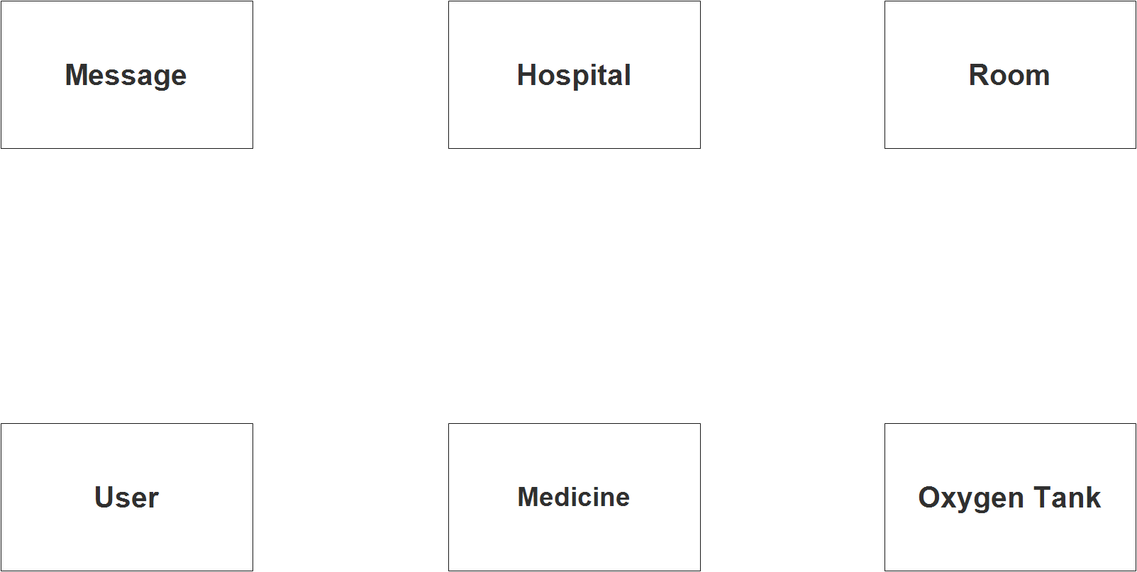
Step 1
In the Hospital Resources and Room Utilization we have the following entities:
- Medicine
- Room
- Oxygen Tank
- Hospital Info
- Message Broadcast
- Users
Our methodology divides the Hospital Resources and Room Utilization System into six tables. Here are the database tables that will eventually comprise the Hospital Resources and Room Utilization database schema. These entities will be included in the database tables.
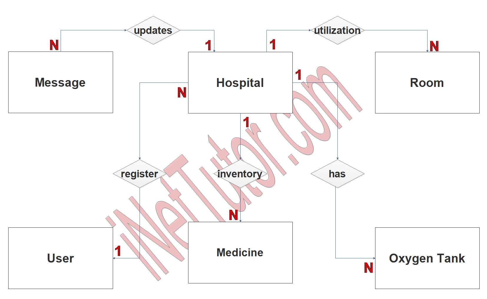
Step 2
After we have specified our entities, it is time now to connect or establish a relationship among the entities.
- The user will register, verify and validate the information of participating hospitals (1 to many relationship).
- The hospital can and will post broadcast messages (1 to many relationship). Authorized personnel can access this feature and post a message for information dissemination purposes.
- Hospital maintains and monitors their medicine inventory (1 to many relationship). Report generation, alerts and notifications are also included in this feature or module of the project.
- Hospital also records and reports the room utilization or bed occupancy (1 to many relationship).
- The project has also a module that will allow hospital to post the availability of their oxygen tanks (1 to many relationship).
Readers are also interested in: Hospital Management System in Laravel 8 Free Source code
Step 3
The last part of the ERD process is to add attributes to our entities.
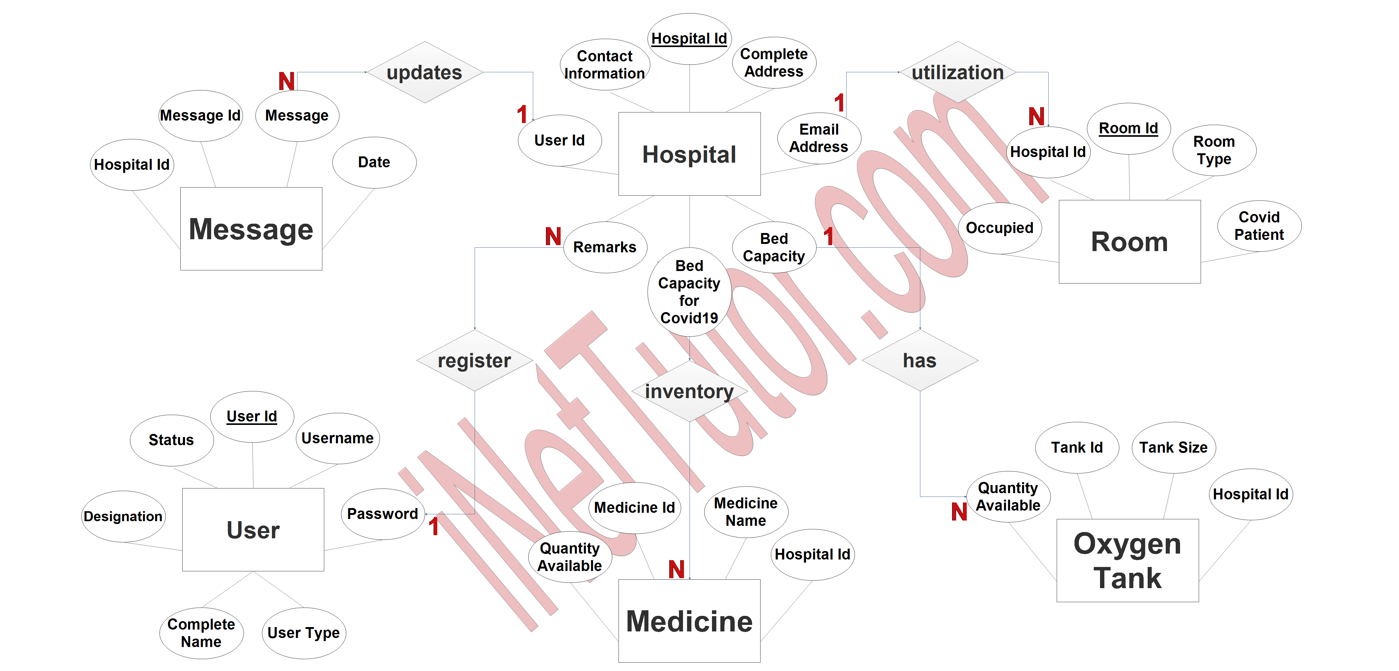
Medicine Entity has the following attributes:
- Medicine ID – primary key represented with underline
- Medicine name
- Hospital ID – foreign key
- Quantity Available
Room Entity has the following attributes:
- Room ID – primary key represented with underline
- Room Type
- COVID Patient
- Occupied
- Hospital ID – foreign key
Oxygen Tank Entity has the following attributes:
- Tank ID – primary key represented with underline
- Tank Size
- Hospital ID – foreign key
- Quantity Available
Hospital Info Entity has the following attributes:
- Hospital ID – primary key represented with underline
- Complete Address
- Contact Information
- Email Address
- Bed Capacity
- Bed Capacity for COVID Patients
- Remarks
- User ID – foreign key
Message Broadcast Entity has the following attributes:
- Message ID – primary key represented with underline
- Message
- Date
- Hospital ID – foreign key
Users Entity has the following attributes:
- User ID – primary key represented with underline
- Username
- Password
- User Type
- Complete name
- Designation
- Account Status
Summary
Entity relationships in a database are graphically represented in an entity relationship diagram, or ER diagram. Anything that can be uniquely identified as one of these entities, including individuals, locations, objects, and ideas, is eligible. Any description of how two entities are related to one another can be used to define their relationships. An ER diagram’s goal is to assist designers and developers in understanding the database structure and how it impacts how data is used. They can also use it to determine which entities are most likely in need of updates or changes. ER diagrams can be used in a variety of disciplines, including software engineering and information systems management, although they are most frequently employed in database design and development.
We hope that this will help you in creating an Entity Relation Diagram for the project related to Hospital Resources and Room Utilization.
In addition, we will also give you a PowerPoint or Video Presentation for the entire ER Diagram. Make sure you visit and subscribe to our YouTube channel to see the videos.
You may visit our Facebook page for more information, inquiries, and comments. Please subscribe also to our YouTube Channel to receive free capstone projects resources and computer programming tutorials.
Hire our team to do the project.