Employee Performance Evaluation System ER Diagram
The capstone project entitled Employee Performance Evaluation System is a web based project that can be deploy on a local area network or online. The evaluation of employee is based on a standard set of questions that will determine their efficiency and accuracy towards their work. The source code of the project is available in Visual Basic (local setup), for the web version the project was written in PHP, MySQL and Bootstrap.
This article will discuss the step by step process on how to prepare the entity relationship diagram or ERD of the project entitled Employee Performance Evaluation System.
The first step in the development of the Employee Performance Evaluation System is to prepare the ER diagram that will serve as the basis later on in the creation of the actual database.
We will create and explain the process of making the entity relationship diagram of Employee Performance Evaluation System.
Let’s start from the symbols used in the ER Diagram.
Entity is represented by the rectangle shape. The entity will be our database table of Employee Performance Evaluation System later on.
Attribute is represented by the oval shape. This will be the columns or fields of each table in the Employee Performance Evaluation System.
Relationship is represented by diamond shape. This will determine the relationships among entities. This is usually in a form of primary key to foreign key connection.
We will follow the 3 basic rules in creating the ER Diagram.
- Identify all the entities.
- Identify the relationship between entities and
- Add meaningful attributes to our entities.
How to Create Employee Performance Evaluation System ER Diagram
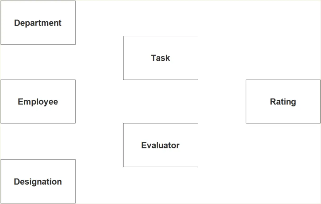
Step 1. In the Employee Performance Evaluation System we have the following entities
- Employee
- Department
- Designation
- Task
- Evaluator
- Rating
Our design of Employee Performance Evaluation System consists of 6 entities; the specified entities will be our database tables in the design and implementation of Employee Performance Evaluation database schema.
We will now draw the entities of the Employee Performance Evaluation System specified above and it will be represented by a rectangle shape. The image below is the entities identified in the scope of the Employee Performance Evaluation System.
Step 2. After we have specified our entities, it is time now to connect or establish a relationship among the entities.
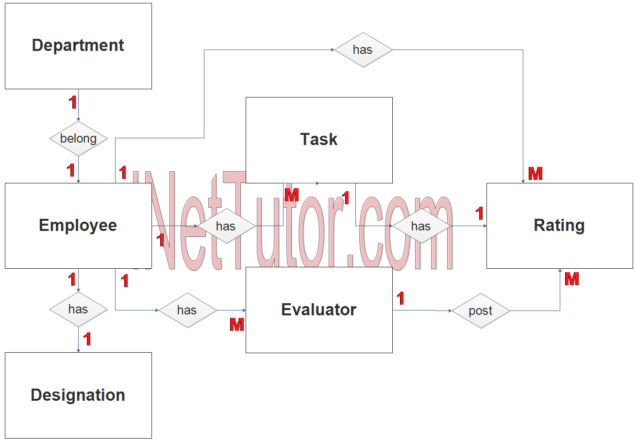
- The employee belongs to a department (1 to 1 relationship).
- The employee has 1 designation but in some cases an employee can have more than 1 designation (1 to 1 relationship).
- The employee has tasks to comply (1 to many relationship).
- The employee will be rated/graded by panel of evaluators (1 to many relationship).
- An evaluator can post the scores for every task (1 to many relationship).
- Every question or task will be rated by evaluators (1 to many relationship).
- The employee can view their scores (1 to many relationship).
Step 3. The last part of the ERD process is to add attributes to our entities.
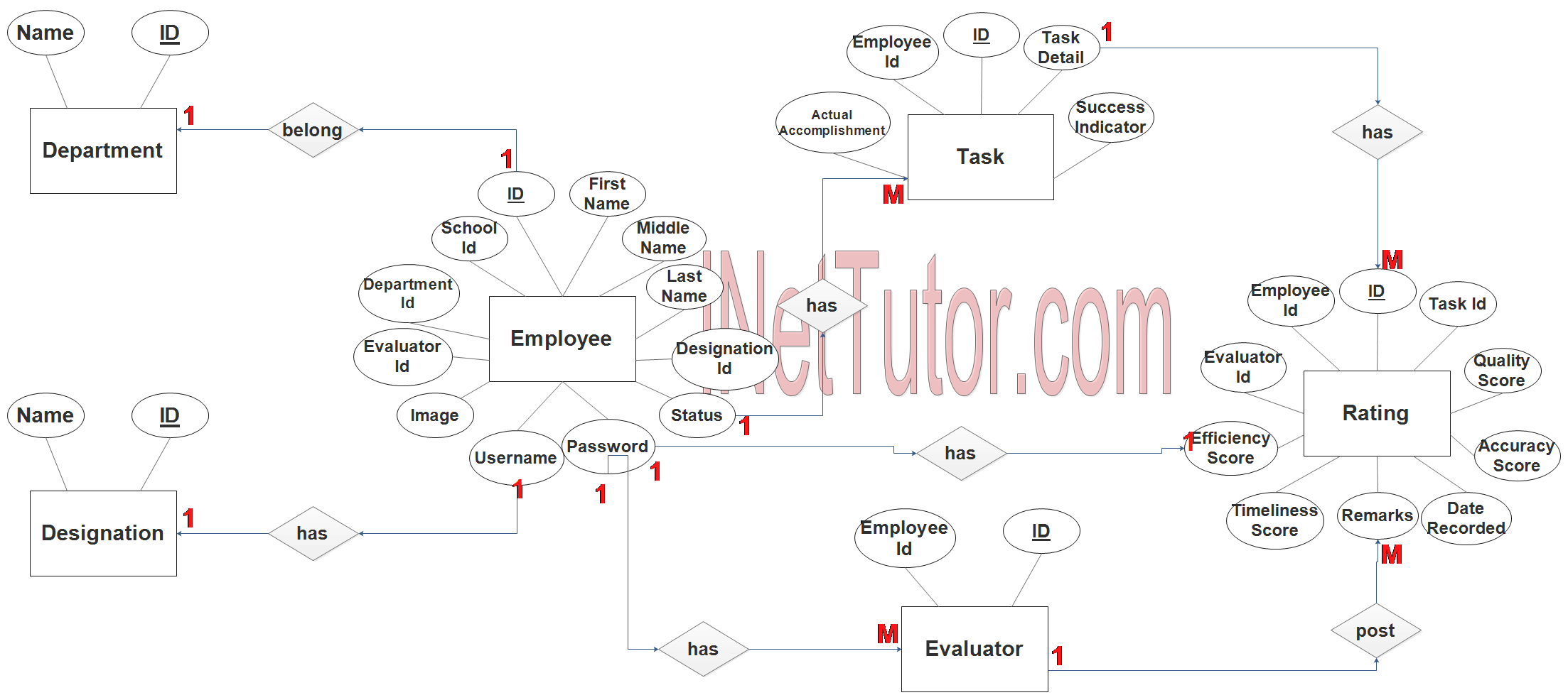
Employee Entity has the following attributes:
- ID – primary key represented with underline
- School ID
- First name
- Middle name
- Last name
- Designation ID – foreign key
- Department ID – foreign key
- Evaluator ID – Foreign key
- Image
- Username
- Password
- Status
Department Entity has the following attributes:
- ID – primary key represented with underline
- Name
Designation Entity has the following attributes:
- ID – primary key represented with underline
- Name
Task Entity has the following attributes:
- ID – primary key represented with underline
- Employee ID –
- Task Detail
- Actual Accomplishment
- Success Indicator
Evaluator Entity has the following attributes:
- ID – primary key represented with underline
- Employee ID – foreign key
Rating Entity has the following attributes:
- ID – primary key represented with underline
- Employee ID – foreign key
- Evaluator ID – foreign key
- Task ID
- Efficiency Score
- Timeliness Score
- Quality Score
- Accuracy Score
- Remarks
- Date Recorded
Note: all attributes with underline represents the primary key of the entity or table.
The next step is to convert the plan designed on ER Diagram into the actual database, please search for the Employee Performance Evaluation System article which was already posted.
This is the softcopy of the ER Diagram of the Employee Performance Evaluation System.
You may visit our Facebook page for more information, inquiries, and comments. Please subscribe also to our YouTube Channel to receive free capstone projects resources and computer programming tutorials.
Hire our team to do the project.