Document Tracking System ER Diagram
This article will walk you through the process of creating an entity relationship diagram, often known as an ERD, for the project entitled Document Tracking System.
Document Tracking System Description
The Document Tracking System is a web-based system that allows authorized users to track the development of documents throughout the document life cycle. It is designed to be used in conjunction with other systems.
The system provides a safe means of tracking the status of documents from the time they are created to the time they are destroyed.
Simple to use, the system gives real-time updates on the progress of documents and is straightforward to navigate.
When it comes to tracking the status of documents throughout the document life cycle, the Document Tracking System is a crucial tool to have. It provides a safe way to track the status of documents from the time they are created until the time they are destroyed. Simple to use, the system gives real-time updates on the progress of documents and is straightforward to navigate. As a result, it is an excellent tool for organizing and controlling your document process. In a variety of situations, including corporate offices and departments, government agencies, and law firms, the Document Tracking System can be used to manage documents. The Document Tracking System (DTS) is an extremely useful tool for organizing and controlling your document process. Document tracking can assist you in tracking the status of documents throughout the document life cycle, ensuring that they are delivered on time and in the proper format.
ERD
There will be two phases to this project: Phase 1 will be the construction of the ER Diagram for the Document Tracking System, and Phase 2 will be the building of the real database that will be used by the system in the future. System for Keeping Track of Documents
We will create an entity relationship diagram for the Document Tracking System as an example, and we will go over the procedures that must be followed in order to complete the diagram generating process successfully. First, let’s go through the various symbols that are used in the ER Diagram and explain what they imply.
The rectangle shape represents the entity that is being shown in the diagram below. At some point in the future, we will use this entity to make a database table for our Document Tracking System.
The shape of a diamond can show how a relationship works, like how it fits together. A lot will depend on this. A primary key to foreign keys relationship is often the best way to do this.
The shape of the oval is a way to show the attribute for the entities specified. Columns or fields will be added to each table in the Document Tracking System, and this will be the case.
We will follow the 3 basic rules in creating the ER Diagram.
- Identify all the entities.
- Identify the relationship between entities and
- Add meaningful attributes to the entities.
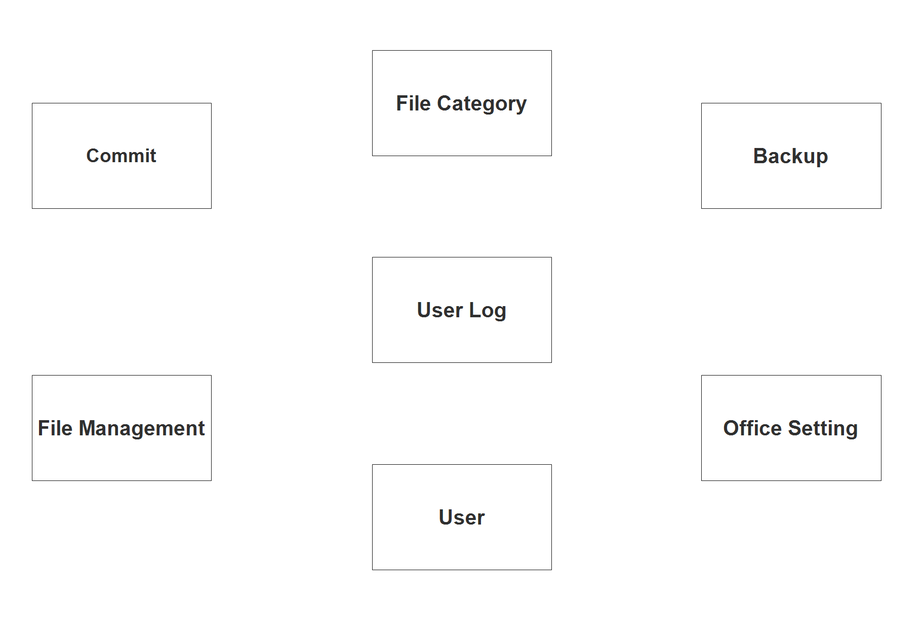
Step 1. In the Document Tracking System we have the following entities:
- Commit
- File Management
- File Category
- User Log
- User
- Backup
- Office Setting
Our methodology divides the Document Tracking System into six tables, each of which contains one document. As we continue to work on the Document Tracking System database schema, the following is a representation of what our database tables will look like as we develop. These entities will be the building blocks of the database tables.
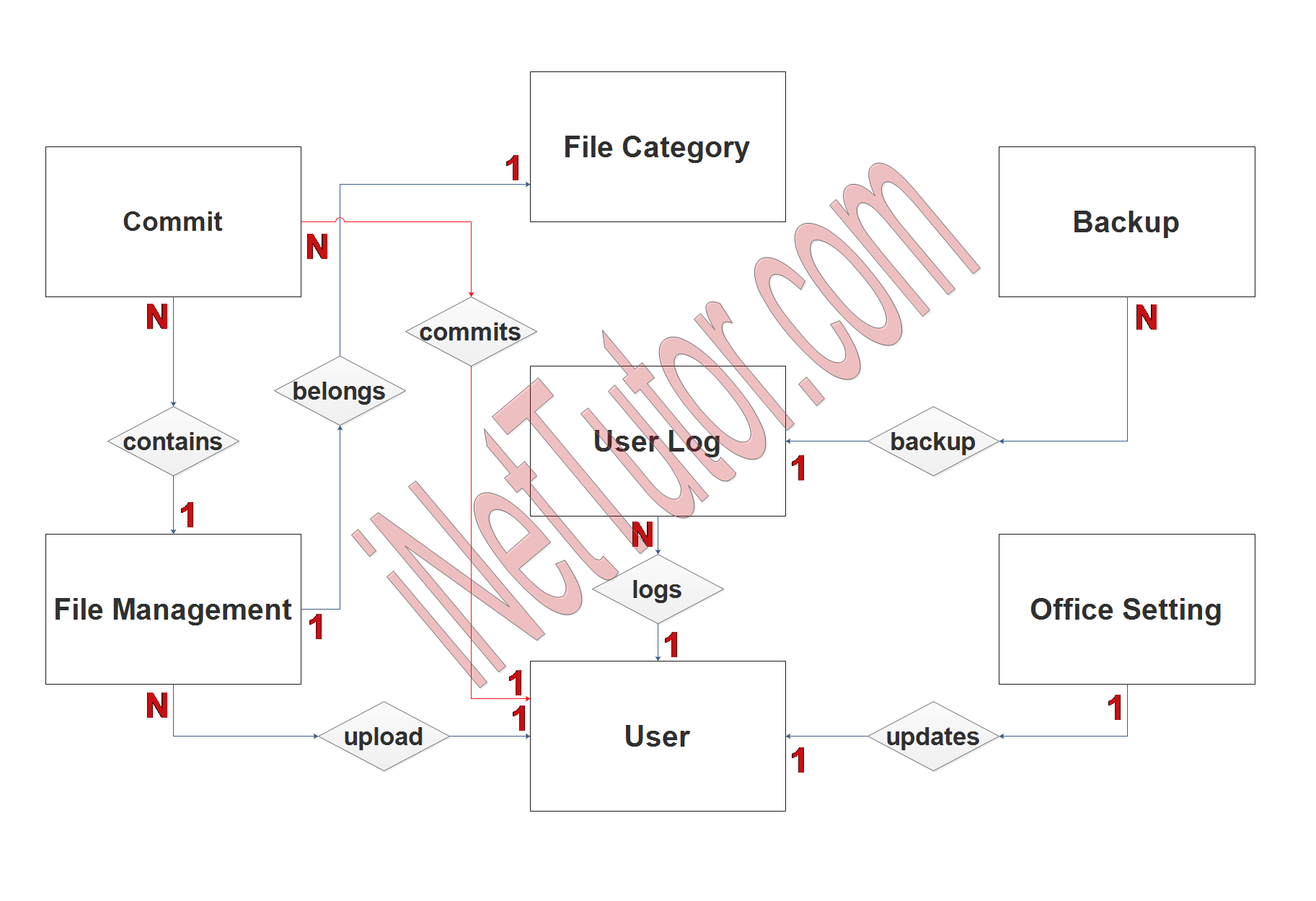
Step 2. After we have specified our entities, it is time now to connect or establish a relationship among the entities.
- Each and every file is a part of a certain group or category (1 to 1 relationship).
- File is being modified and revised and it is stored in the commit table or record (1 to many relationship).
- The user may upload 1 or more files in the project (1 to many relationship).
- The user updates the file and it is reflected in the commit table in order to monitor the updates of the user (1 to many relationship).
- The activity of the user in the system such as the login, upload and commit are all recorded in the user log table (1 to many relationship).
- The user with admin access can perform the backup feature of the project (1 to many relationship).
- The user can also update the information of the company or office (1 to 1 relationship).
Step 3. The last part of the ERD process is to add attributes to our entities.
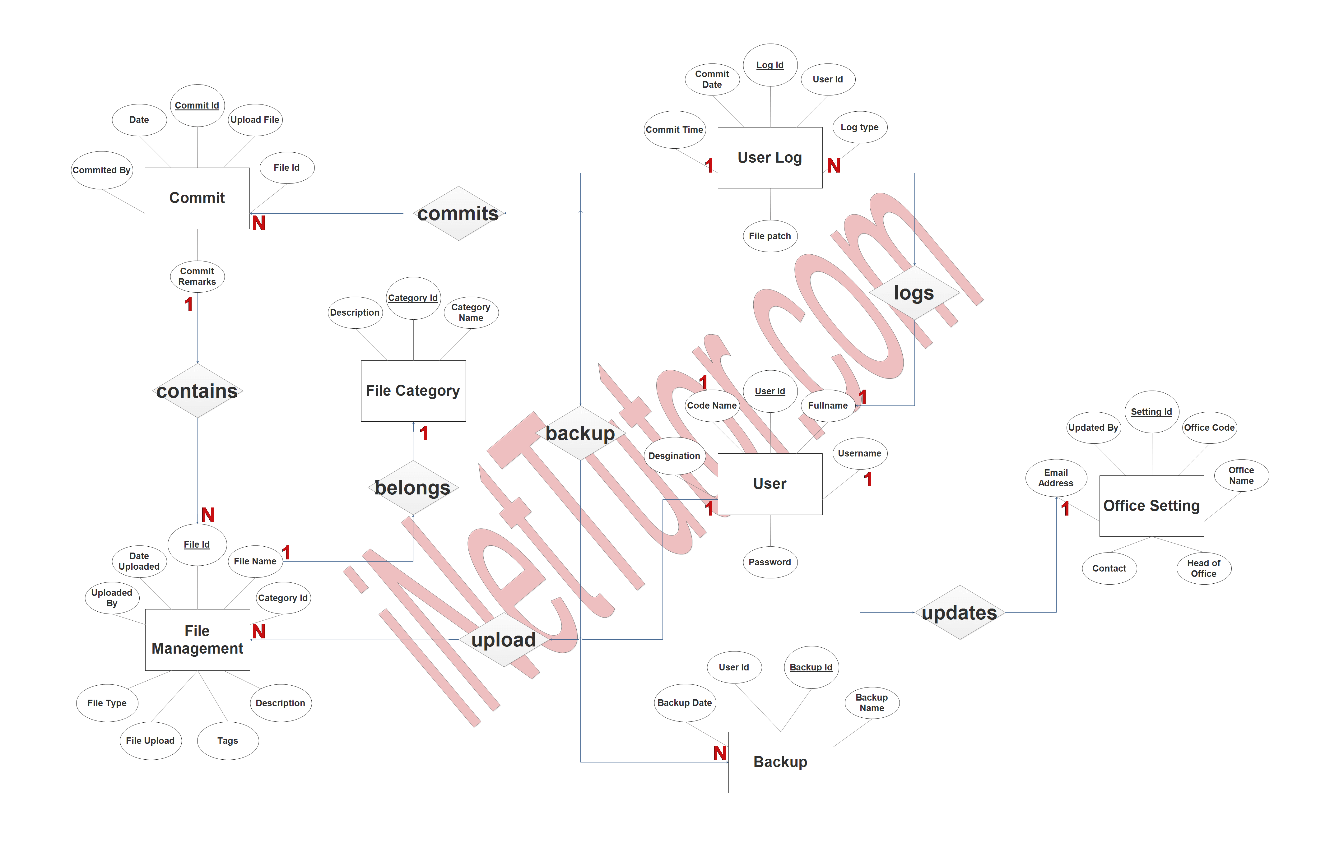
Commit Entity has the following attributes:
- Commit ID – primary key represented with underline
- Upload file
- File ID – foreign key
- Commit remarks
- Committed by – foreign key
- Date
File Management Entity has the following attributes:
- File ID – primary key represented with underline
- File name
- Category ID
- Description
- Tags
- File upload
- File type
- Uploaded by
- Date uploaded
File Category Entity has the following attributes:
- Category ID – primary key represented with underline
- Category name
- Description
User Log Entity has the following attributes:
- Log ID – primary key represented with underline
- User ID – foreign key
- Log type
- File path
- Commit time
- Commit date
User Entity has the following attributes:
- User ID – primary key represented with underline
- Full name
- Username
- Password
- Designation
- Code name
Backup Entity has the following attributes:
- Backup ID – primary key represented with underline
- Backup name
- Backup date
- User ID – foreign key
Office Setting Entity has the following attributes:
- Setting ID – primary key represented with underline
- Office code
- Office name
- Head of office
- contact
- email address
Summary
A document tracking system can provide a number of advantages for an organization. These advantages can include:
- Reduced lost or misplaced documents
- Easier retrieval of documents
- Increased efficiency and productivity
- Fewer delays in getting work done
- Better control over documents and their distribution
- More accurate and up-to -date information about documents and their status
- Reduced cost of document management
- Improved security for documents
For the purpose of developing and documenting the database structure, an ER diagram is an important tool to have on hand. In addition to assisting you in comprehending how the tables in your database are related to one another, it may also assist you in creating and modifying your database structure.
In addition, we will also give you a PowerPoint or Video Presentation for the entire ER Diagram. Make sure you visit and subscribe to our YouTube channel to see the videos.
You may visit our Facebook page for more information, inquiries, and comments. Please subscribe also to our YouTube Channel to receive free capstone projects resources and computer programming tutorials.
Hire our team to do the project.
Related Topics and Articles:
Document Tracking System Free Download
Document Tracking System Database Design Tutorial
Online School Documents Processing System Free Database Design Tutorial
Student Academic Performance Tracking and Monitoring System
IT Capstone Project with Proposal and Complete Documentation
