Tele Medicine Information System ER Diagram
This article will walk you through the process of creating an entity relationship diagram, often known as an ERD, for the project entitled Tele Medicine Information System.
Tele Medicine Information System Description
Diagnostics, treatment, education, and counseling are just a few of the services that can be provided by telemedicine.
It is possible for patients to access Tele Medicine services from anywhere in the world.
Telecommunications medicine, or telemedicine, is now being used to provide healthcare services to people all around the world.
The following are some of the most popular Telemedicine services:
- Medical condition diagnosis and treatment: Telemedicine can be used to diagnose and treat a wide range of medical disorders. The treatment of ailments such as cancer, heart disease, and diabetes is included in this category. Telemedicine also enables the diagnosis of rare diseases in underdeveloped countries, which was previously impossible.
- Patient education and counseling: Telemedicine can be utilized to give patients with educational and counseling materials and services. This involves offering information on medical diseases, treatments, and therapies, as well as making referrals. Moreover, it may assist patients in making informed decisions regarding their health-care options.
- Provision of healthcare services: Telemedicine can be utilized to provide healthcare services to patients. 4. Provision of services: This can include providing medical treatment, offering educational services, and providing counseling services, among other things.
- Collaborative care: Patients can benefit from the usage of telemedicine in order to receive collaborative treatment. Provide care from a variety of healthcare professionals at the same time falls under this category. It may also make it possible for information to be shared between different healthcare providers.
ERD
This is the first phase of the Tele Medicine Information System’s development, and it will serve as the foundation for the building of the system’s actual database in the future. Information System for Telemedicine
We will create an entity relationship diagram using the Tele Medicine Information System as an example and discuss the techniques that must be followed to complete the diagram development. Let’s start with the symbols used in the ER Diagram and talk about what they imply.
The entity depicted in the diagram below is represented by the rectangular form. We’ll use this item to create a database table for our Tele Medicine Information System at some time in the future.
A diamond’s shape can reveal how a relationship functions, such as how it fits together. This will have a significant impact. The ideal approach to do this is to use a main key to foreign key relationship.
The shape of the oval is a way to show the attribute for the entities specified. Columns or fields will be added to each table in the Tele Medicine Information System, and this will be the case.
We will follow the 3 basic rules in creating the ER Diagram.
- Identify all the entities.
- Identify the relationship between entities and
- Add meaningful attributes to our entities.
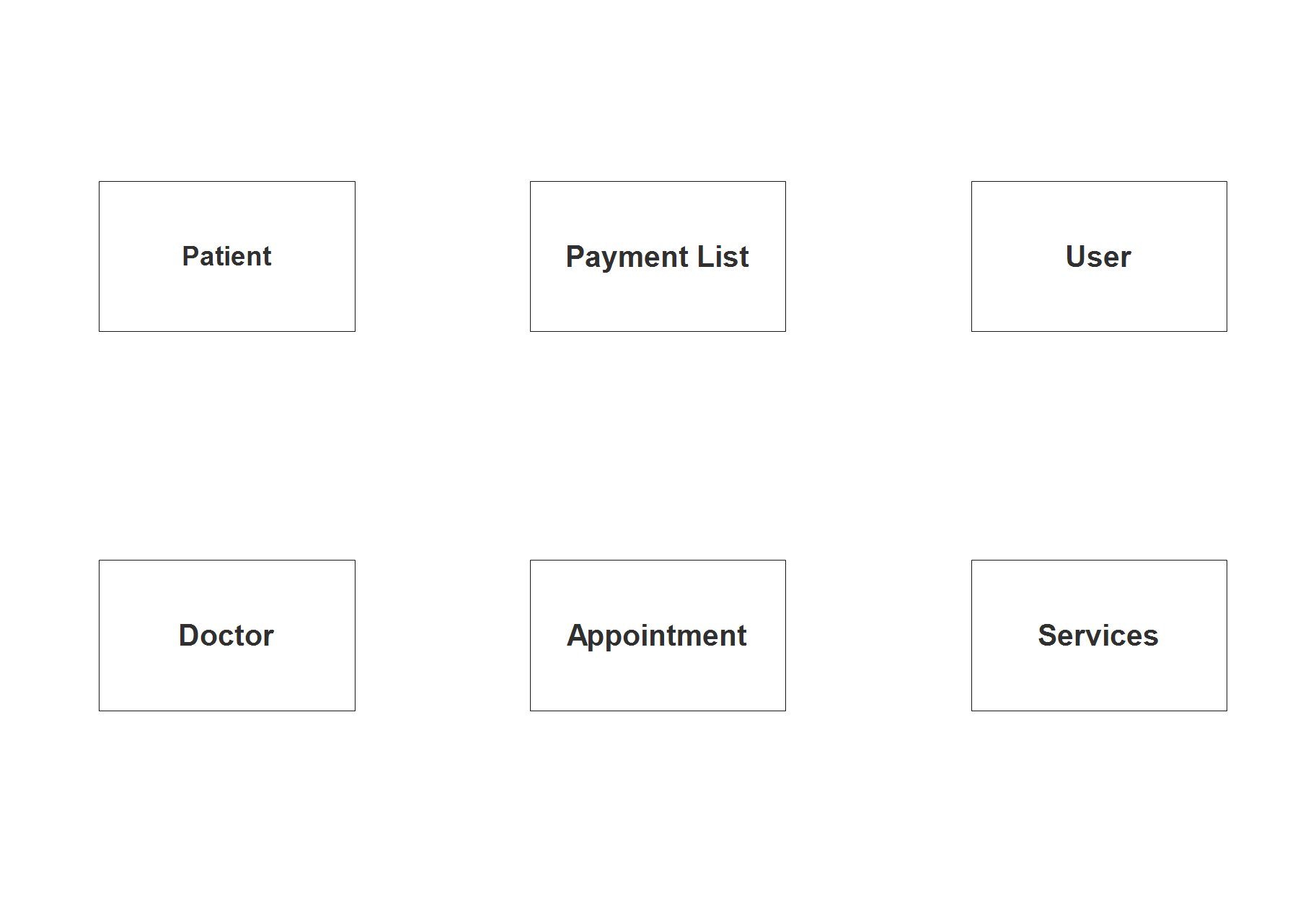
Step 1. In the Tele Medicine Information System we have the following entities:
- Patient
- Doctor
- Appointment
- Payment List
- Services
- User
The Tele Medicine Information System is divided into six tables, according to our methodology. As we work on the Tele Medicine Information System database schema, here is what our database tables will look like as we progress. The database tables will be made up of these entities.
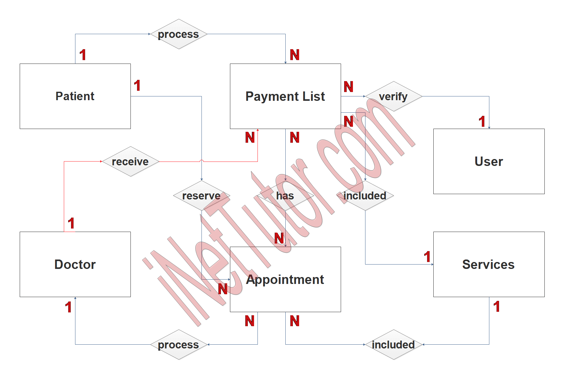
Step 2. After we have specified our entities, it is time now to connect or establish a relationship among the entities.
- The patient or representative can process their reservation in the appointment module of the project. The patient record may appear more than once in the appointment record but the patient can only process a reservation one at a time (1 to many relationship).
- The patient or representative can process the payments through the payment module of the system. Patient information may appear multiple times in the payment records (1 to many relationship).
- The doctor can process the appointments. Doctor can cancel, accept and reschedule the appointments based on their availability. (1 to many relationship).
- The doctor can view the list of payments in the payment records (1 to many relationship).
- List of services are also included in the billing statement with their corresponding amount or service fee (1 to many relationship).
- The patient can select the services they want for it is a part of the appointment reservation (1 to many relationship).
- System users can process and verify the payment transactions (1 to many relationship).
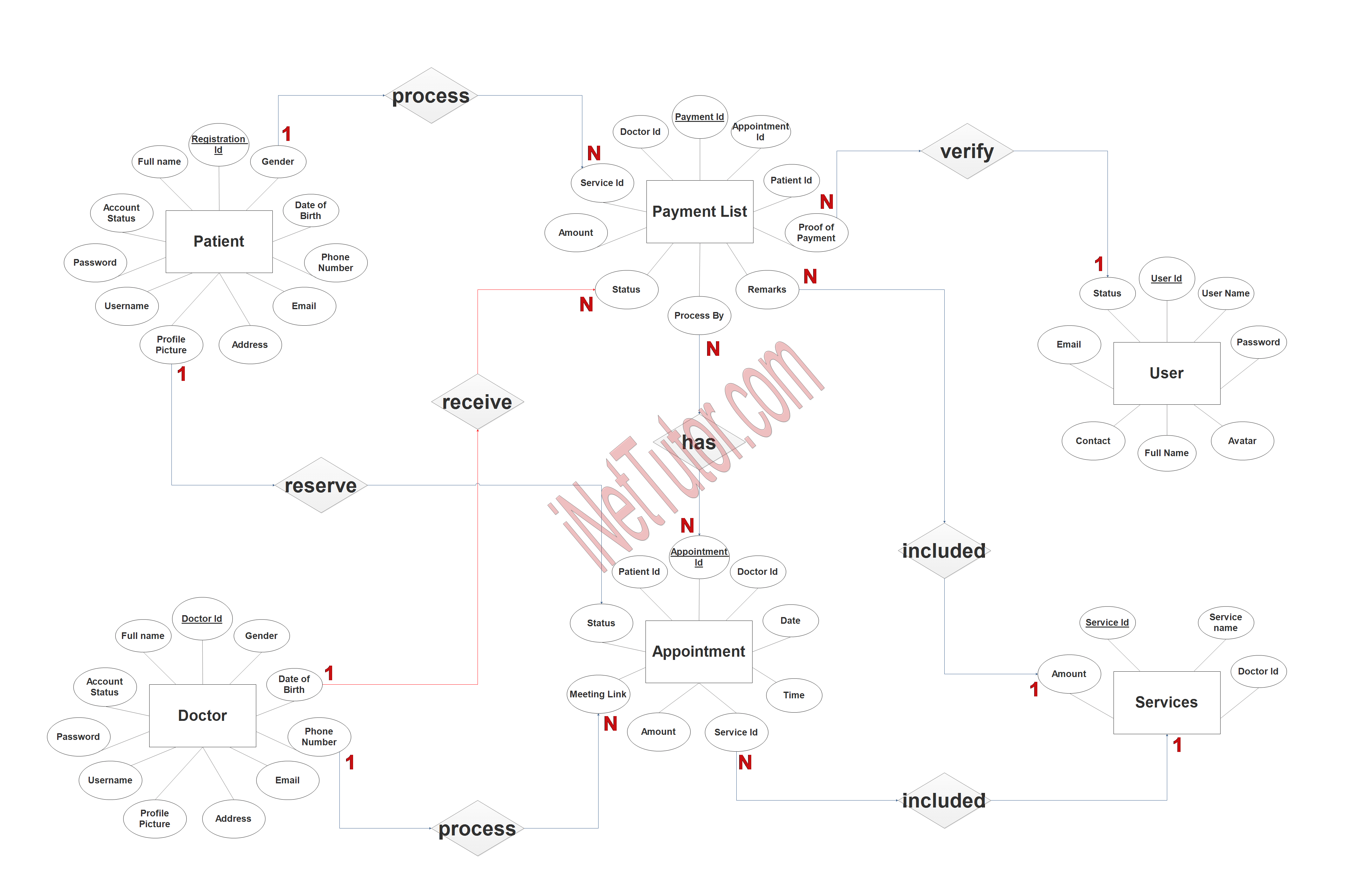
Step 3. The last part of the ERD process is to add attributes to our entities.
Patient Entity has the following attributes:
- Registration ID – primary key represented with underline
- Full name
- Gender
- Date of birth
- Phone number
- Address
- Profile picture
- Username
- Password
- Account status
Doctor Entity has the following attributes:
- Doctor ID – primary key represented with underline
- Full name
- Gender
- Qualification
- Profile picture
- Contact
- Clinic map
- Username
- Password
- Account status
Appointment Entity has the following attributes:
- Appointment ID – primary key represented with underline
- Doctor ID – foreign key
- Patient ID – foreign key
- Date
- Time
- Service ID – foreign key
- Amount
- Meeting link
- Status
Payment List Entity has the following attributes:
- Payment ID – primary key represented with underline
- Appointment ID – foreign key
- Doctor ID – foreign key
- Patient ID
- Service ID
- Amount
- Proof of payment
- Status
- Remarks
- Processed by
Services Entity has the following attributes:
- Service ID – primary key represented with underline
- Service name
- Amount
- Doctor ID
User Entity has the following attributes:
- User ID – primary key represented with underline
- Username
- Password
- Avatar
- Full name
- Contact
- Status
Summary
The value of ERD in software development cannot be overstated. ERD is a graphical depiction of a database’s structure. It’s used to represent the database’s entities as well as their relationships. This ensures that the database is properly built and that all required entities are there. It’s also possible to use it to create database schemas.
The database tables can also be created with ERD. This is significant since it guarantees the database’s data is accurate and architecturally sound. It can also aid in the creation of a database that is simple to use and comprehend. ERD can also be used to generate SQL statements for database management.
We hope that this will help you in creating an Entity Relation Diagram for the project related to Tele Medicine Information System.
In addition, we will also give you a PowerPoint or Video Presentation for the entire ER Diagram. Make sure you visit and subscribe to our YouTube channel to see the videos.
You may visit our Facebook page for more information, inquiries, and comments. Please subscribe also to our YouTube Channel to receive free capstone projects resources and computer programming tutorials.
Hire our team to do the project.
Related Topics and Articles:
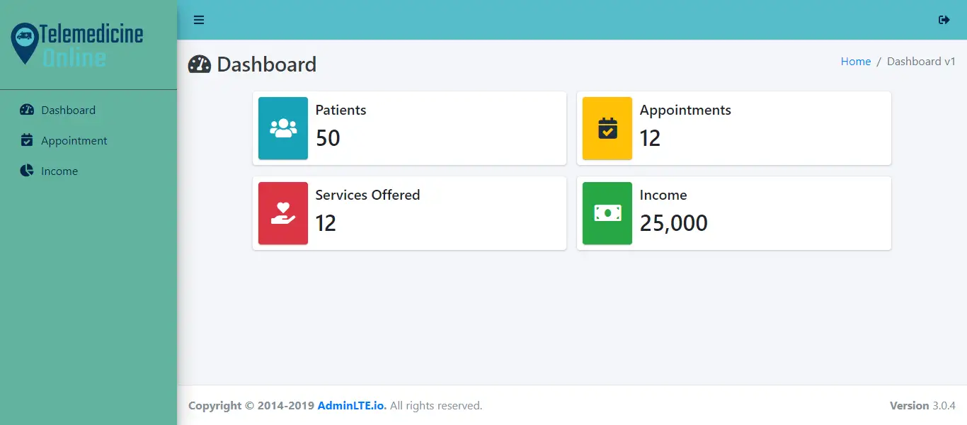
Telemedicine Online Platform Free Bootstrap Template
COVID-19 Facilities Management Information System Database Design
EDelivery Platform in PHP and MySQL with Source code
IPO Model Conceptual Framework of Pharmacy Stocks Management System