Law Office Management Information System ER Diagram
This article will discuss the step-by-step process on how to prepare the entity relationship diagram or ERD of the project entitled Law office Management Information System.
About the Project
Table of Contents
Law Office Management Information System is designed to streamline law firm office’s daily operations and transactions. The said project will automate recording, storing, and management of client’s records, attorney’s records, services records, payment records, and other activities in the firm. The records and other documents of the firm will be stored in a database and is accessible by authorized personnel for easy retrieval.
The case management module of LOMIS allows attorneys to create, manage and track the progress of their cases. It typically includes features such as case intake, case tracking, and reporting. The client management module allows the law office to maintain a database of clients, including their contact information, case history, billing information, and other relevant details.
A Law Office Management Information System (LOMIS) is a computer-based system that is designed to support the day-to-day operations of a law office. The system typically includes a variety of modules that handle different aspects of the law office’s work, such as case management, client management, billing and accounting, document management, and scheduling.
LOMIS is an essential tool for any law office, helping to streamline processes, improve communication, and increase efficiency by providing a centralized location for managing and tracking the law office’s cases, clients, and financials.
ER Diagram
The first step in the development of the Law Office Management Information System is to prepare the ER diagram that will serve as the basis later on in the creation of the actual database.
We will create and explain the process of making the entity relationship diagram of Law Office Management Information System.
Let’s start from the symbols used in the ER Diagram.
Entity is represented by the rectangle shape. The entity will be our database table of Law Office Management Information System later on.
Attribute is represented by the oval shape. This will be the columns or fields of each table in the Law Office Management Information System.
Relationship is represented by diamond shape. This will determine the relationships among entities. This is usually in a form of primary key to foreign key connection.
We will follow the 3 basic rules in creating the ER Diagram.
- Identify all the entities.
- Identify the relationship between entities and
- Add meaningful attributes to our entities.
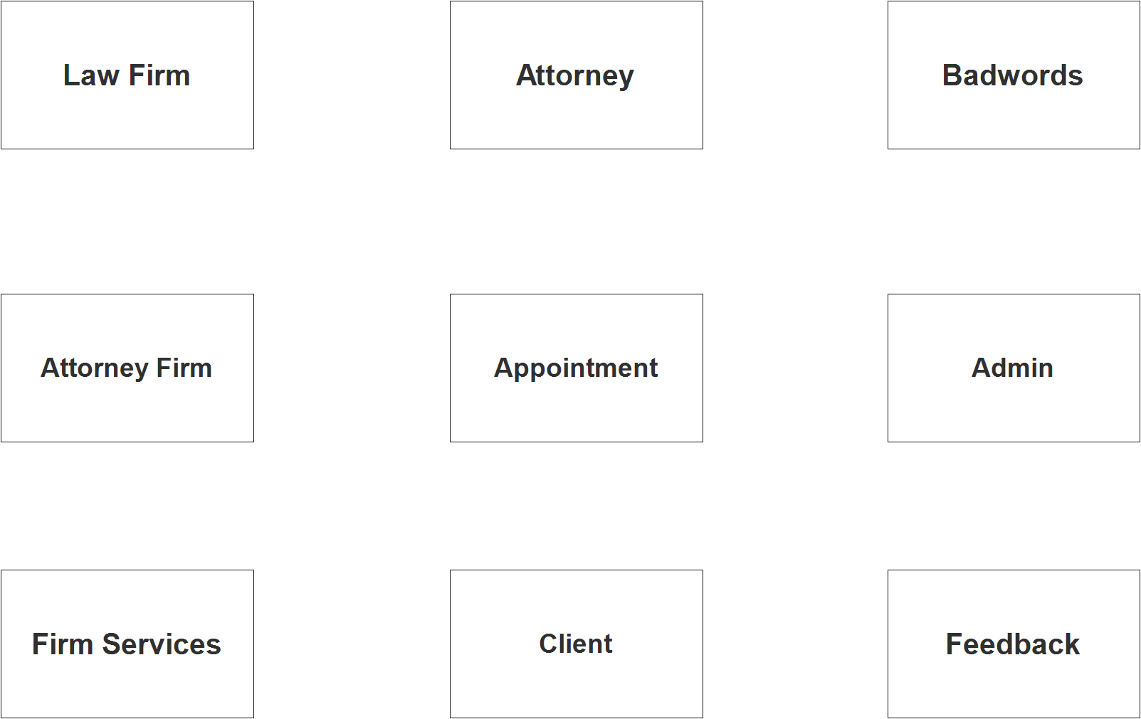
Step 1. Identify Entities
In the Law Office Management Information System, we have the following entities
- Law Firm
- Firm Services
- Appointment
- Client
- Feedback
- Attorney Firm
- Attorney
- Badwords
- Admin
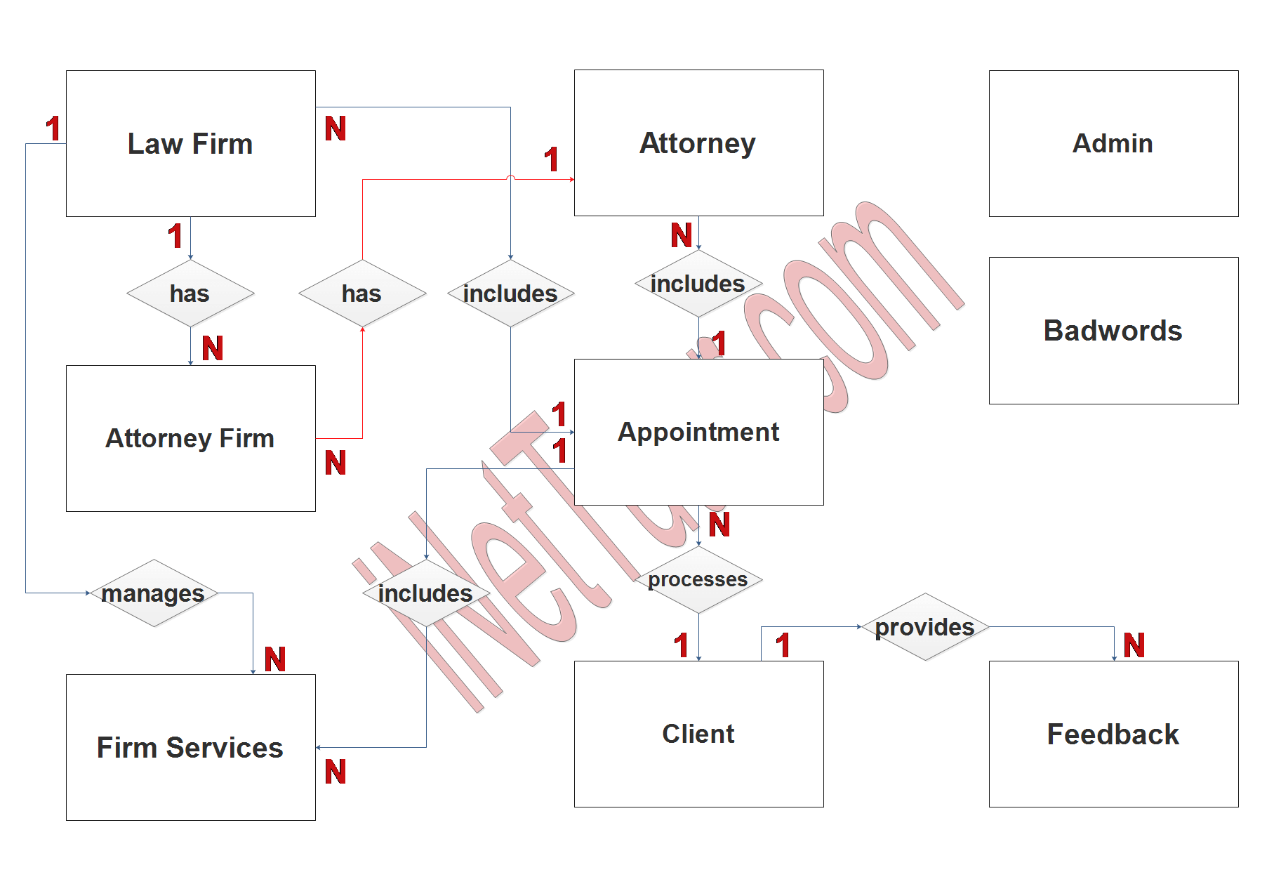
We will now draw the entities of the Law Office Management Information System specified above and it will be represented by a rectangle shape. The image below are the entities identified in the scope of the project management system.
Step 2. Establish Relationships
After we have specified our entities, it is time now to connect or establish a relationship among the entities.
The relationships between the tables in the database describe the associations and dependencies between the data stored in each table.
- attorney_id has tbl_attorney_firm.attorney_id (1:N) – This relationship represents that one attorney can be associated with multiple attorney firms and each attorney firm can have one attorney.
- firm_id manages tbl_attorney_firm.attorney_id (1:N) – This relationship represents that one law firm can manage multiple attorney firms and each attorney firm can be managed by one law firm.
- firm_id has tbl_firm_services.firm_id (1:N) – This relationship represents that one law firm can offer multiple services and each service can be offered by one law firm.
- attorney.id includes tbl_attorney.attorney_id (1:N) – This relationship represents that one appointment can include one attorney and an attorney can have multiple appointments.
- firm_id includes tbl_law_firm.firm_id (1:N) – This relationship represents that one appointment can include one law firm and a law firm can have multiple appointments.
- service_id includes tbl_firm_services.service_id (1:N) – This relationship represents that one appointment can include one service and a service can have multiple appointments.
- client_id processes tbl_appointment.client_id (1:N) – This relationship represents that one client can have multiple appointments and each appointment can have one client.
- client_id provides tbl_feedback.client_id (1:N) – This relationship represents that one client can provide multiple feedbacks and each feedback can be provided by one client.
Step 3. Add Meaningful Entities
The last part of the ERD process is to add attributes to our entities.
Law Firm entity has the following attributes:
- Firm_id – Primary Key
- Firm_name
- Complete_address
- Contact_info
- Email_address
- Website
- Facebook_page
- History
Firm Services entity has the following attributes:
- Service_id – primary key
- Service_name
- Description
- Firm_id – foreign key
- Attorney_id -foreign key
- Rate
Appointment entity has the following attributes:
- Appointment_id – primary key
- Client_id -foreign key
- Firm_id – foreign key
- Attorney_id-foreign key
- Service_id – foreign key
- Reference_number
- Remarks
- Status
Client entity has the following attributes:
- Client_id – primary key
- Client_lastname
- Client_firstname
- Client_middlename
- Contact
- Email_address
- Valid_id – foreign key
- Username
- Password
- Account_status
Feedback entity has the following attributes:
- Feedback_id – primary key
- Client_id -foreign key
- Message
- Rate
- Status
Attorney Firm entity has the following attributes:
- Record_id – primary key
- Attorney_id – foreign key
- Firm_id – foreign key
Attorney entity has the following attributes:
- Attorney_id – primary key
- Last_name
- First_name
- Middle_name
- Gender
- Complete_address
- Contact_details
- Tax
- Profile_picture
- Education
- Professional_experience
- Username
- Password
- Account_status
Badwords entity has the following attributes:
- Word_id – primary key
- Bad_word
Admin entity has the following attributes:
- Admin_id – primary key
- Admin_user
- Admin_pass
- Complete_name
- Email_address
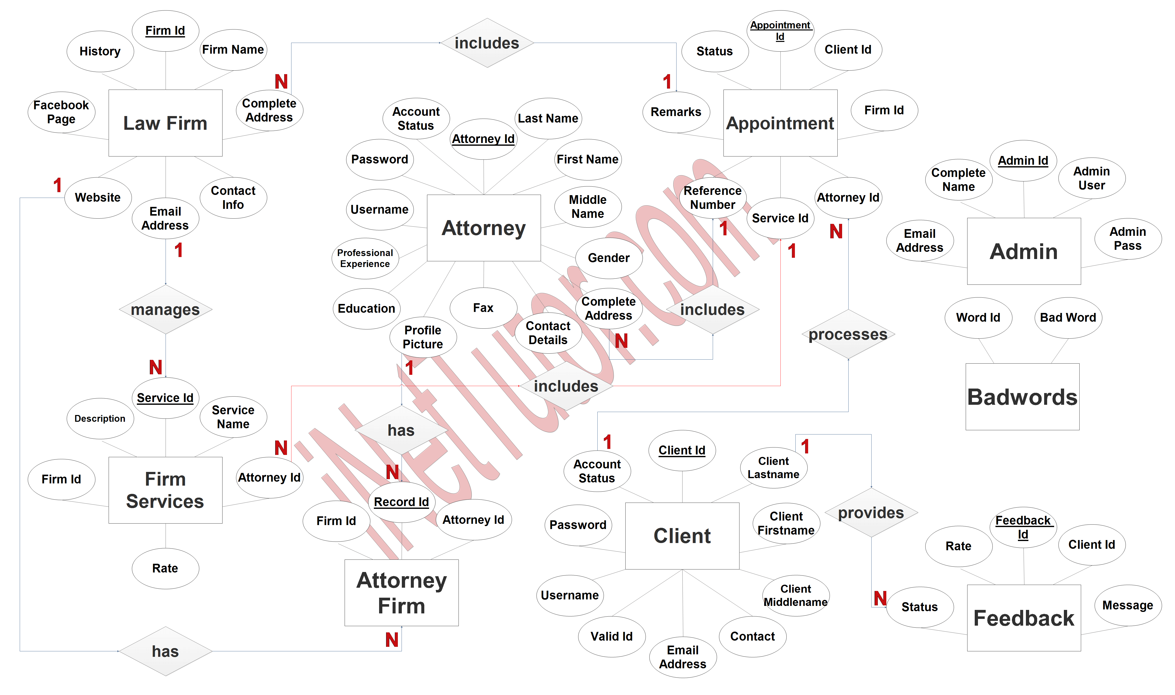
Note: all attributes with underline represents the primary key of the entity or table.
The next step is to convert the plan designed on ER Diagram into the actual database, please search for the Law Office Management Information System article which was already posted.
Summary
An ER (entity-relationship) diagram is a powerful tool that can be used to model and design a Law Office Management Information System (LOMIS). The ER diagram is a graphical representation of the entities, attributes, and relationships that make up the system, providing a clear and concise view of the system’s data and functionality.
In the case of LOMIS, the main entities include clients, attorneys, law firms, appointments, services, and feedbacks. Each of these entities has a set of attributes that describe its characteristics, such as name, address, and contact information. The relationships between these entities are represented by lines connecting the entities, with different symbols used to indicate the type of relationship, such as one-to-many or many-to-many.
In conclusion, an ER diagram is a valuable tool for the development of a Law Office Management Information System, providing a clear and concise view of the system’s data and functionality, and helping to ensure that the system meets the needs of the stakeholders and is able to handle the real-world scenarios.
Readers are also interested in:
IPO Model Conceptual Framework of Law Office Management Information System
Law Office Management Information System in Bootstrap and PHP Script
You may visit our Facebook page for more information, inquiries, and comments. Please subscribe also to our YouTube Channel to receive free capstone projects resources and computer programming tutorials.
Hire our team to do the project.