Real Estate Property Management System ER Diagram
The capstone project entitled Real Estate Property Management System is an online platform that allows real property owners/agents to post their real estate property. With this project the clients and customers who want to avail a real estate property can visit and browse the items posted on the platform and can communicate directly to the owners and agent.
This article will discuss the step by step process on how to prepare the entity relationship diagram or ERD of the project entitled Real Estate Property Management System.
The first step in the development of the Real Estate Property Management System is to prepare the ER diagram that will serve as the basis later on in the creation of the actual database.
We will create and explain the process of making the entity relationship diagram of Real Estate Property Management System.
Let’s start from the symbols used in the ER Diagram.
Entity is represented by the rectangle shape. The entity will be our database table of Real Estate Property Management System later on.
Attribute is represented by the oval shape. This will be the columns or fields of each table in the Real Estate Property Management System.
Relationship is represented by diamond shape. This will determine the relationships among entities. This is usually in a form of primary key to foreign key connection.
We will follow the 3 basic rules in creating the ER Diagram.
- Identify all the entities.
- Identify the relationship between entities and
- Add meaningful attributes to our entities.
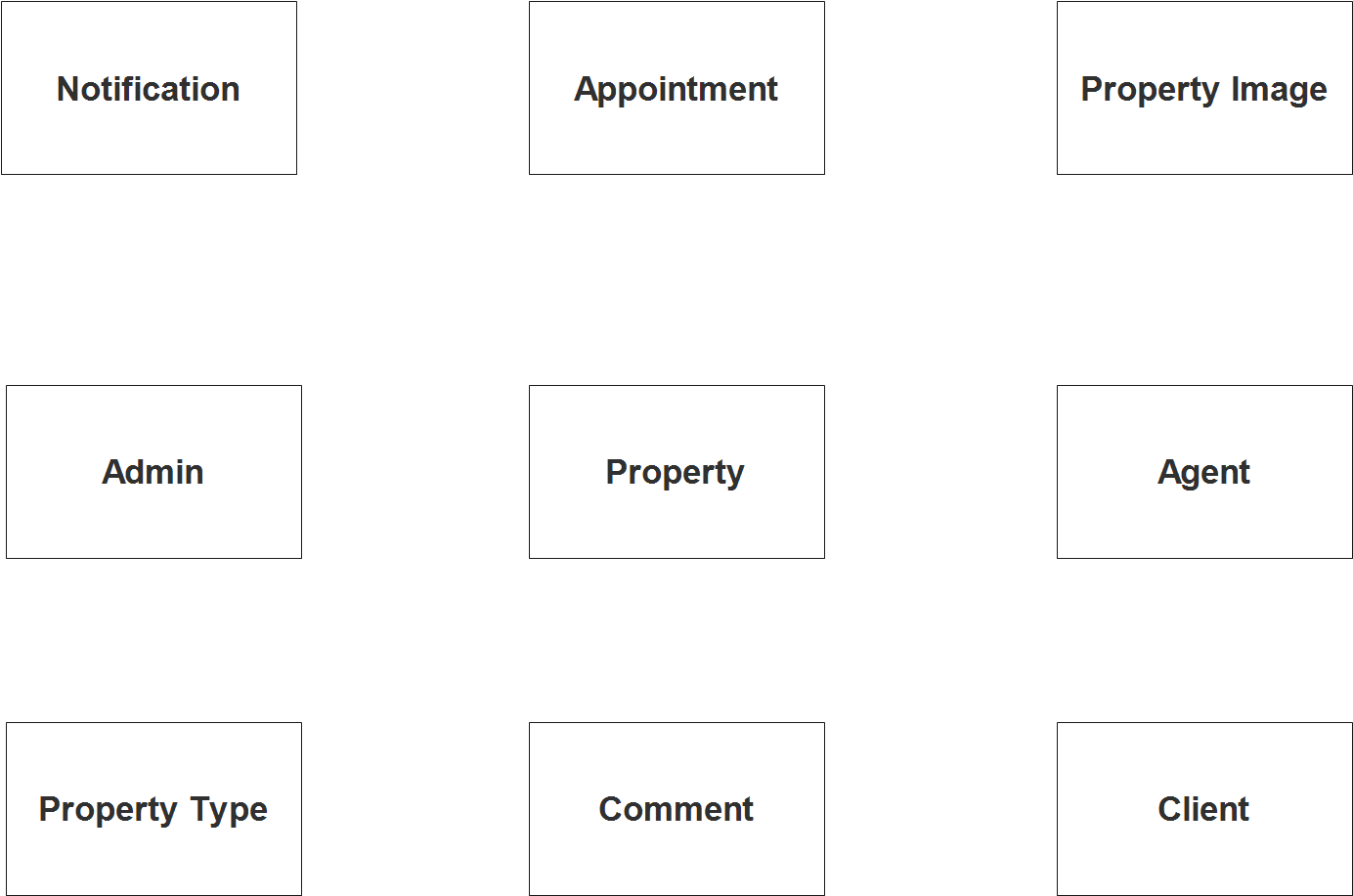
Step 1. In the Real Estate Property Management System we have the following entities
- Admin
- Notification
- Appointment
- Comment
- Client
- Agent
- Property
- Property Type
- Property Image
Our design of Real Estate Property Management System consists of 9 entities; the specified entities will be our database tables in the design and implementation of Real Estate Property Management database schema.
We will now draw the entities of the Real Estate Property Management System specified above and it will be represented by a rectangle shape. The image below is the entities identified in the scope of the Real Property Estate Management System.
Step 2. After we have specified our entities, it is time now to connect or establish a relationship among the entities.
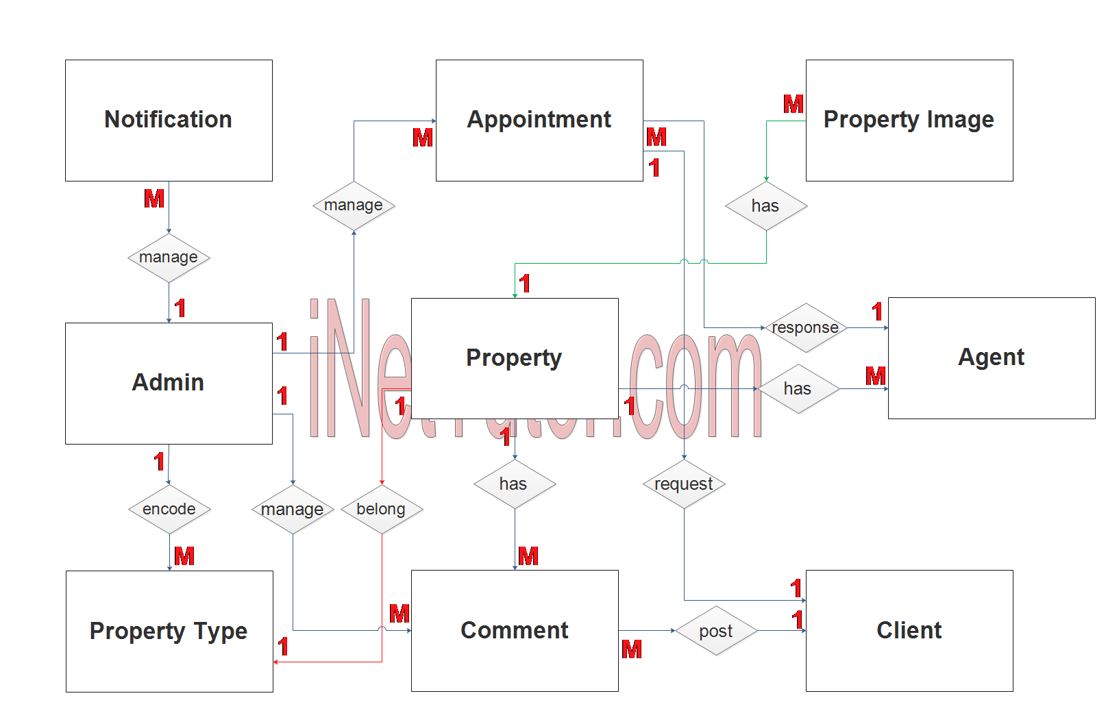
- The admin or moderator encode/manage/update the property type information (1 to many relationship).
- The admin or moderator encode/manage/update the messages, news, updates and other notification (1 to many relationship).
- The admin or moderator manages the appointment transactions (1 to many relationship).
- The admin or moderator manages the comments (1 to many relationship).
- The property belongs to a property type (1 to 1 relationship).
- The property has multiple images (1 to many relationship).
- The property is being promoted by multiple real estate agents (1 to many relationship).
- The client requests for an appointment or meeting (1 to 1 relationship).
- The client can also post comments (1 to many relationship).
- Agents can response to the appointment requested by the client (1 to many relationship).
Step 3. The last part of the ERD process is to add attributes to our entities.
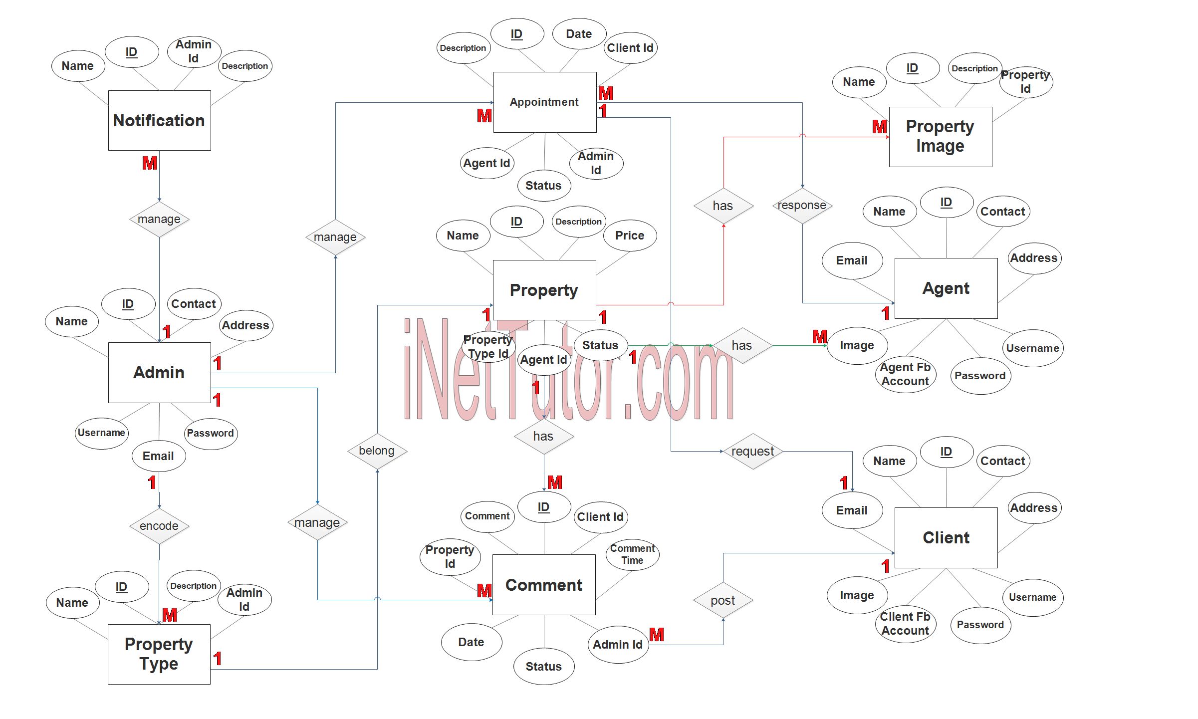
Admin Entity has the following attributes:
- ID – primary key represented with underline
- Name
- Contact
- Address
- Username
- Password
Notification Entity has the following attributes:
- ID – primary key represented with underline
- Name
- Description
- Admin ID – foreign key
Appointment Entity has the following attributes:
- ID – primary key represented with underline
- Description
- Date
- Client ID – foreign key
- Agent ID – foreign key
- Admin ID – foreign key
- Status
Comment Entity has the following attributes:
- ID – primary key represented with underline
- Name
- Description
- Admin ID – foreign key
Client Entity has the following attributes:
- ID – primary key represented with underline
- Name
- Contact
- Address
- Image
- Client FB Account
- Username
- Password
Agent Entity has the following attributes:
- ID – primary key represented with underline
- Name
- Contact
- Address
- Image
- Agent FB Account
- Username
- Password
Property Entity has the following attributes:
- ID – primary key represented with underline
- Name
- Description
- Price
- Property Type ID – foreign key
- Agent ID – foreign key
- Status
Property Type Entity has the following attributes:
- ID – primary key represented with underline
- Name
- Description
- Admin ID – foreign key
Property Image Entity has the following attributes:
- ID – primary key represented with underline
- Name
- Description
- Property ID – foreign key
Note: all attributes with underline represents the primary key of the entity or table.
The next step is to convert the plan designed on ER Diagram into the actual database, please search for the Real Estate Management System article which was already posted.
Contact us on our facebook page for the softcopy of the Real Estate Management System.
You may visit our facebook page for more information, inquiries and comments.
Hire our team to do the project.