Project Management System ER Diagram
This article will discuss the step by step process on how to prepare the entity relationship diagram or ERD of the project entitled Project Management System.
Project Management System is an information system that will manage the processes and transactions involved in monitoring and recording the updates of a project. The said project can be implemented in an offline settings but in most cases this is implemented in a live server or it simply means an online system.
The first step in the development of the Project Management System is to prepare the ER diagram that will serve as the basis later on in the creation of the actual database.
We will create and explain the process of making the entity relationship diagram of project management system.
Let’s start from the symbols used in the ER Diagram.
Entity is represented by the rectangle shape. The entity will be our database table of Project Management System later on.
Attribute is represented by the oval shape. This will be the columns or fields of each table in the Project Management System.
Relationship is represented by diamond shape. This will determine the relationships among entities. This is usually in a form of primary key to foreign key connection.
We will follow the 3 basic rules in creating the ER Diagram.
- Identify all the entities.
- Identify the relationship between entities and
- Add meaningful attributes to our entities.
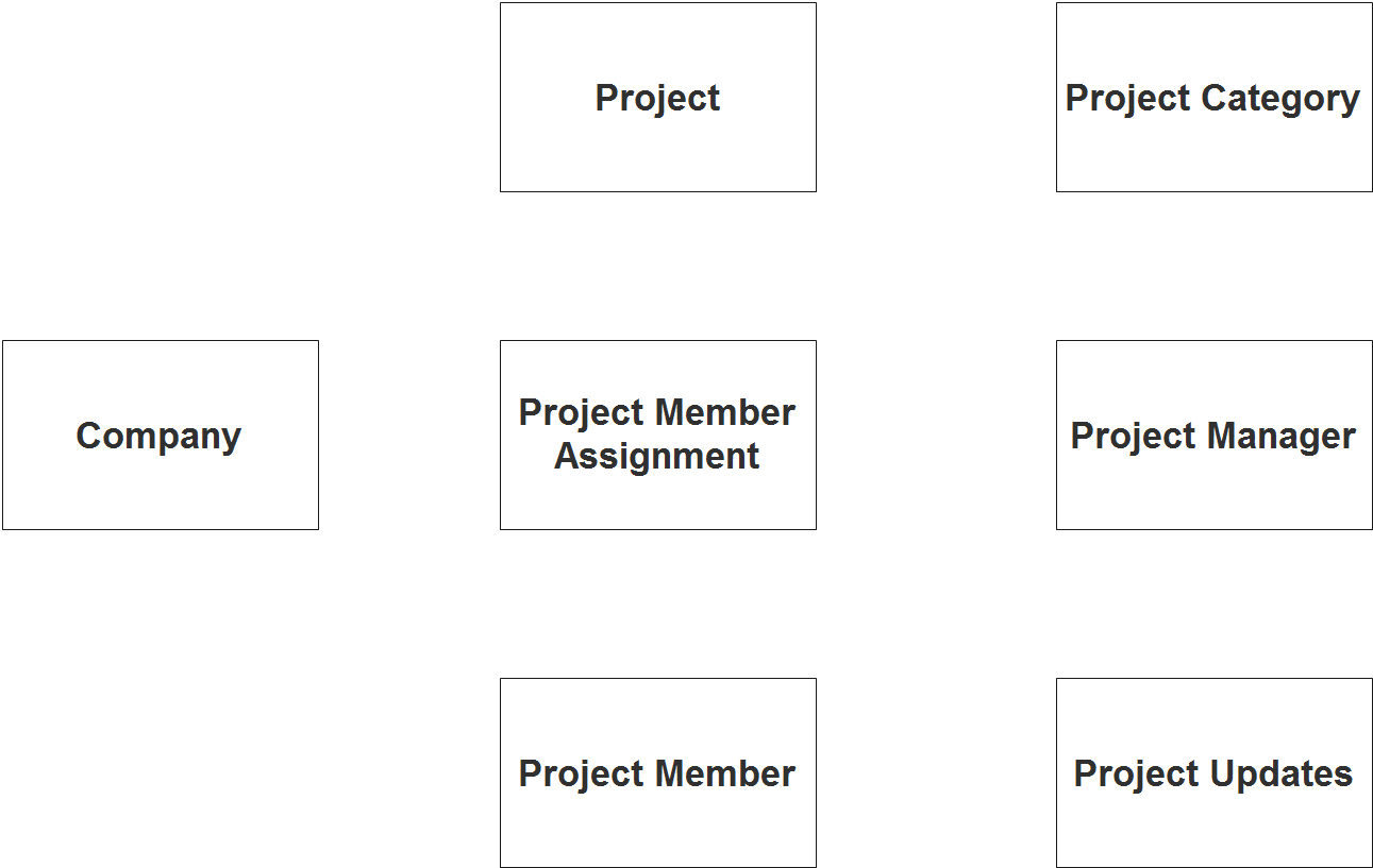
Step 1. In the Project Management System we have the following entities
- Company
- Project
- Project Category
- Project Member Assignment
- Project Member
- Project Manager
- Project Updates
We will now draw the entities of the Project Management System specified above and it will be represented by a rectangle shape. The image below are the entities identified in the scope of the project management system.
Step 2. After we have specified our entities, it is time now to connect or establish a relationship among the entities.
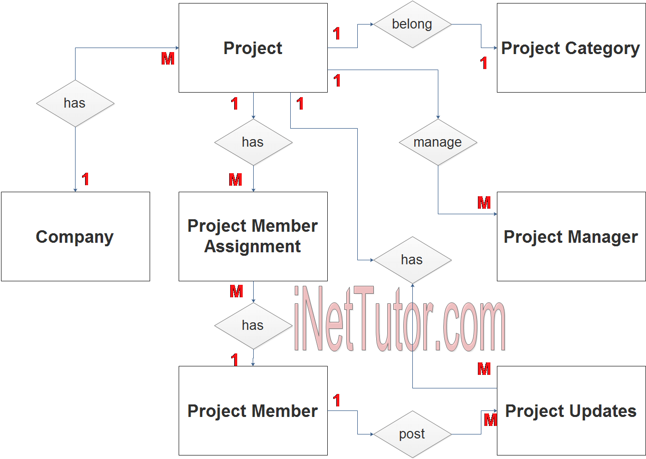
- company has 1 or more projects to be managed (1 to many relationship).
- the project belongs to a specific type or category (1 to 1 relationship).
- the project can be managed by multiple project managers, it depends of the scope of the project, but to be more flexible the relationship will be set to (1 to many relationship).
- The project will be assigned to several members (1 to many relationship).
- The project member can be assigned to several tasks (1 to many relationship).
- The project member posts an updates (1 to many relationship).
- The project will receive an updates (1 to many relationship).
Step 3. The last part of the ERD process is to add attributes to our entities.
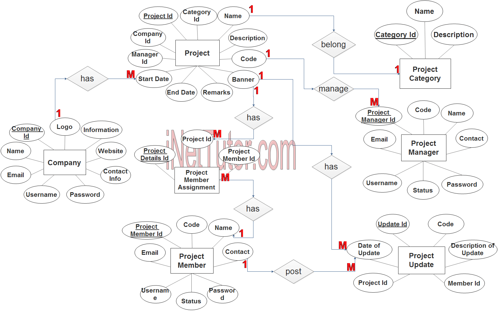
Company Entity has the following attributes:
- Company ID – primary key represented with underline
- Name
- Logo
- Information
- Website
- Contact information
- Username
- Password
Project Entity has the following attributes:
- Project ID – primary key represented with underline
- Company ID – foreign key
- Category ID – foreign key
- Manager ID – foreign key
- Name
- Description
- Code
- Banner
- Start Date
- End Date
- Remarks
Project Category Entity has the following attributes:
- Category ID – primary key represented with underline
- Name
- Description
Project Member Assignment Entity has the following attributes:
- Project Details ID – primary key represented with underline
- Project ID – foreign key
- Project Member ID – foreign key
Project Member Entity has the following attributes:
- Project Member ID – primary key represented with underline
- Code
- Name
- Contact
- Username
- Password
- Status
Project Manager Entity has the following attributes:
- Project Manager ID – primary key represented with underline
- Code
- Name
- Contact
- Username
- Password
- Status
Project Update Entity has the following attributes:
- Update ID – primary key represented with underline
- Code
- Date of Update
- Description of Update
- Project ID
- Member ID
Note: all attributes with underline represents the primary key of the entity or table.
The next step is to convert the plan designed on ER Diagram into the actual database, please search for the Project Management System article which was already posted.
Contact us on our facebook page for the softcopy of the Project Management System.
You may visit our facebook page for more information, inquiries and comments.
Hire our team to do the project.