Point of Sale System (POS) ER Diagram
Point of Sale System or POS is a database oriented information system primarily intended to monitor the sales and inventory processes of an organization. Our team has a point of sale system written in visual basic and ms access, visual basic and mysql, c# and mysq, web and mobile version is currently under development.
The said system is a network based or online platform wherein the client or the terminal is connected to the central server that stores the database and records of the system.
This article will discuss the step by step process on how to prepare the entity relationship diagram or ERD of the project entitled Point of Sale System (POS).
The first step in the development of the Point of Sale System (POS) is to prepare the ER diagram that will serve as the basis later on in the creation of the actual database.
We will create and explain the process of making the entity relationship diagram of point of sale system.
Let’s start from the symbols used in the ER Diagram.
Entity is represented by the rectangle shape. The entity will be our database table of Point of Sale System (POS) later on.
Attribute is represented by the oval shape. This will be the columns or fields of each table in the Point of Sale System (POS).
Relationship is represented by diamond shape. This will determine the relationships among entities. This is usually in a form of primary key to foreign key connection.
We will follow the 3 basic rules in creating the ER Diagram.
- Identify all the entities.
- Identify the relationship between entities and
- Add meaningful attributes to our entities.
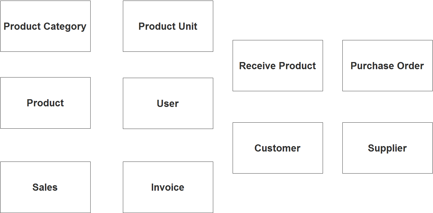
Step 1. In the Point of Sale System (POS) we have the following entities
- Product
- Product Category
- Product Unit
- Sales
- Invoice
- Receive Product
- Customer
- Supplier
- Purchase Order
- User
We will now draw the entities of the Point of Sale System (POS) specified above and it will be represented by a rectangle shape. The image below is the entities identified in the scope of the Point of Sale System (POS).
Step 2. After we have specified our entities, it is time now to connect or establish a relationship among the entities.
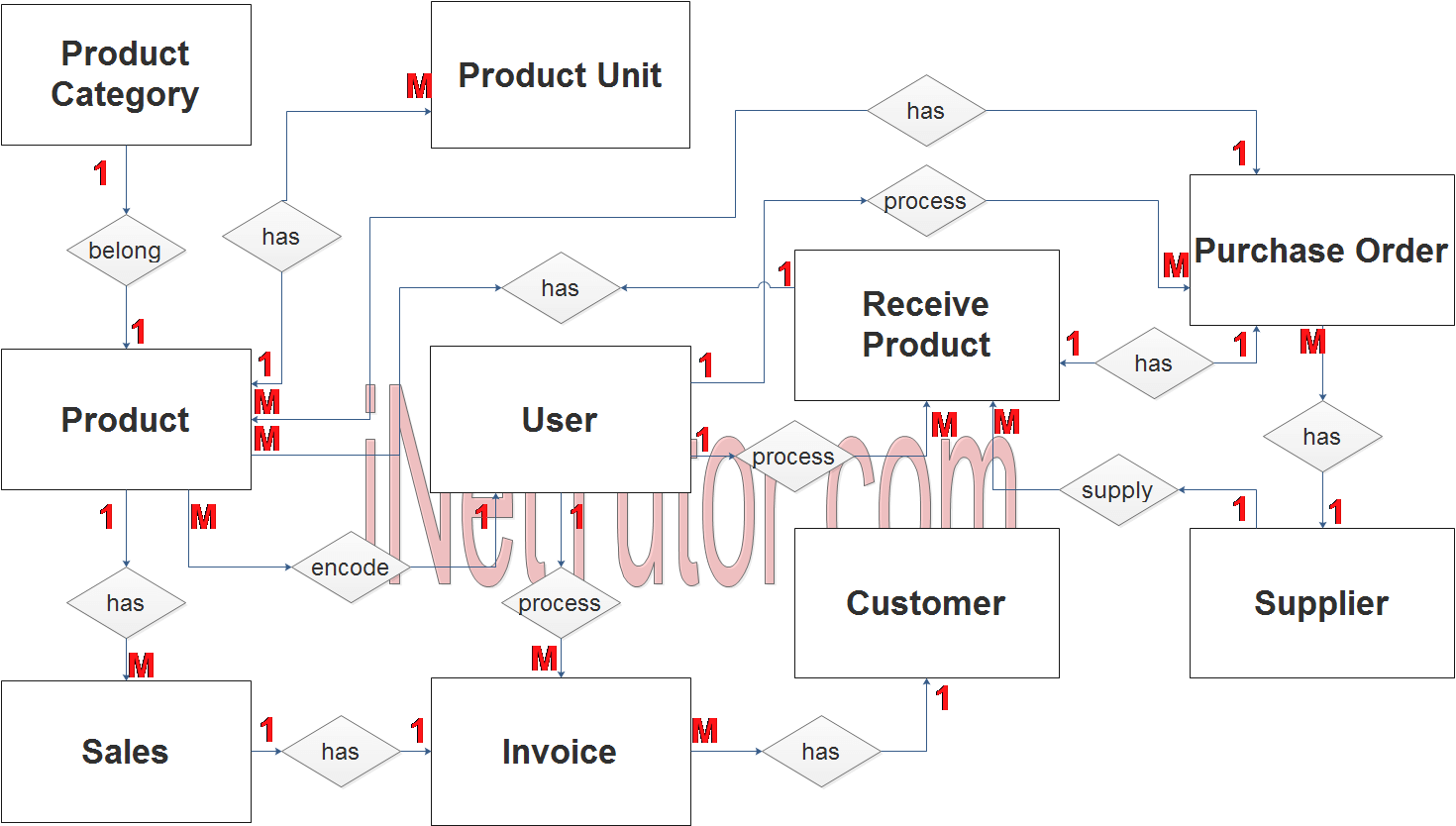
- The user encodes the products (1 to many relationship).
- The user can process multiple invoices (1 to many relationship).
- The user can process the receiving transactions (1 to many relationship).
- The user can process the purchase order transactions (1 to many relationship).
- product belongs to a certain category (1 to 1 relationship).
- product has multiple product units (1 to many relationship).
- product has multiple receiving transactions (1 to many relationship).
- product is also included in the purchase order transaction (1 to many relationship).
- purchase order will be forwarded to the supplier (1 to many relationship).
- The supplier will supply the requested products (1 to many relationship).
- product is included in multiple sales transaction (1 to many relationship).
- sales produce an invoice (1 to many relationship).
- An invoice is given to the customer (1 to many relationship).
Step 3. The last part of the ERD process is to add attributes to our entities.
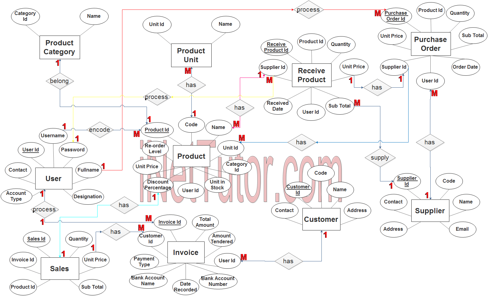
Product Entity has the following attributes:
- Product ID – primary key represented with underline
- Code
- Name
- Unit Price
- Unit in Stock
- Discount Percentage
- Re Order Level
- Category ID – foreign key
- Unit ID – foreign key
- User ID – foreign key
Product Category Entity has the following attributes:
- Category ID – primary key represented with underline
- Name
Product Unit Entity has the following attributes:
- Unit ID – primary key represented with underline
- Name
Sales Entity has the following attributes:
- Sales ID – primary key represented with underline
- Invoice ID – foreign key
- Product ID – foreign key
- Quantity
- Unit Price
- Sub Total
Invoice Entity has the following attributes:
- Invoice ID – primary key represented with underline
- Customer ID – foreign key
- Total Amount
- Amount Tendered
- Payment Type
- Bank Account Name
- Bank Account Number
- Date Recorded
- User ID – foreign key
Receive Product Entity has the following attributes:
- Receive Product ID – primary key represented with underline
- Product ID – foreign key
- Quantity
- Unit Price
- Sub Total
- Received Date
- Supplier ID – foreign key
- User ID – foreign key
Customer Entity has the following attributes:
- Customer ID – primary key represented with underline
- Code
- Name
- Contact Address
Supplier Entity has the following attributes:
- Supplier ID – primary key represented with underline
- Code
- Name
- Contact
- Address
Purchase Order Entity has the following attributes:
- Purchase Order ID – primary key represented with underline
- Product ID – foreign key
- Quantity
- Unit Price
- Sub Total
- Order Date
- Supplier ID – foreign key
- User ID – foreign key
User Entity has the following attributes:
- User ID – primary key represented with underline
- Fullname
- Contact
- Designation
- Account Type
- Username
- Password
Note: all attributes with underline represents the primary key of the entity or table.
The next step is to convert the plan designed on ER Diagram into the actual database, please search for the Point of Sale System (POS) article which was already posted.
Contact us on our facebook page for the softcopy of the Point of Sale System (POS).
You may visit our facebook page for more information, inquiries and comments.
Hire our team to do the project.