Driving School System ER Diagram
This article will describe the step by step procedure on how to construct the entity relationship diagram or ERD of the project entitled Driving School System.
Driving School System Description
When it comes to a city’s total transportation infrastructure, the driving school system is an extremely vital component. It is in charge of instructing new drivers on how to operate motor vehicles in a safe and effective manner.
- What is the purpose of this document?
For driving school businesses, the objective of this system is to give a convenient and efficient way to manage their operations. Businesses will be able to manage their student information, plan classes, and track payments through the use of this system.
- Requirements for the system
A computer with internet access as well as a web browser will be required to use the system.
- Design Criteria for a System
The system will include the following features:
- System security will be provided.
- Make it possible for people to create and remove their own accounts.
- Students can establish their own profile with personal information such as their name, address, phone number, and email address, among other things.
- Students can upload, edit, and delete photos from their profile.
For more information, please visit the link below to know more about the driving school management system.
Driving School System ERD
The first phase in the development of the Driving School System is the preparation of the ER diagram, which will later be used as the basis for the creation of the actual database that will be used in the system.
We will develop an entity relationship diagram for the Driving School System and describe the steps involved in creating the diagram.
Let us begin with the symbols that are used in the ER Diagram.
The rectangle shape represents the entity being represented. Later on, we will use this entity to create a database table for our Driving School System.
The oval form represents the attribute being represented. The Driving School System will have columns or fields for each table, and this will be the case.
The diamond shape represents the nature of a relationship. The relationships between entities will be determined by this. This is often accomplished through the use of a primary key to foreign key relationship.
We will follow the 3 basic rules in creating the ER Diagram.
- Identify all the entities.
- Identify the relationship between entities and
- Add meaningful attributes to our entities.
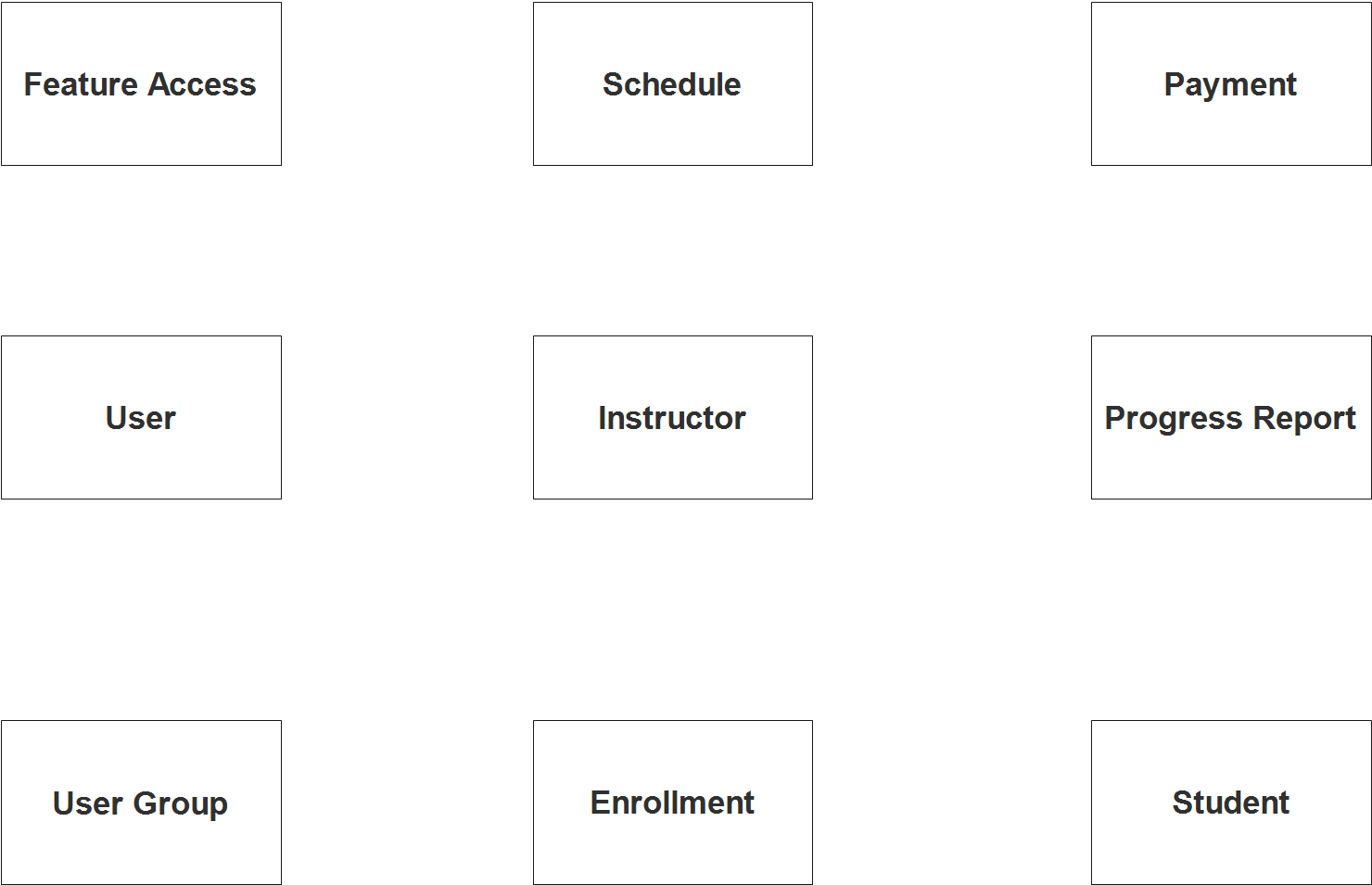
Step 1. In the Driving School System we have the following entities:
- User
- User Group
- Feature Access
- Instructor
- Schedule
- Enrollment
- Student
- Progress Report
- Payment
Our design for the Driving School System has nine components. The components that make up these parts will be the segments of our database tables when we design and build the Driving School System database schema.
We are now going to draw the things that make up the Driving School System, and they will be shown in the shape of a rectangle. The image below is the entities identified in the scope of the Driving School System.
Step 2. After we have specified our entities, it is time now to connect or establish a relationship among the entities.
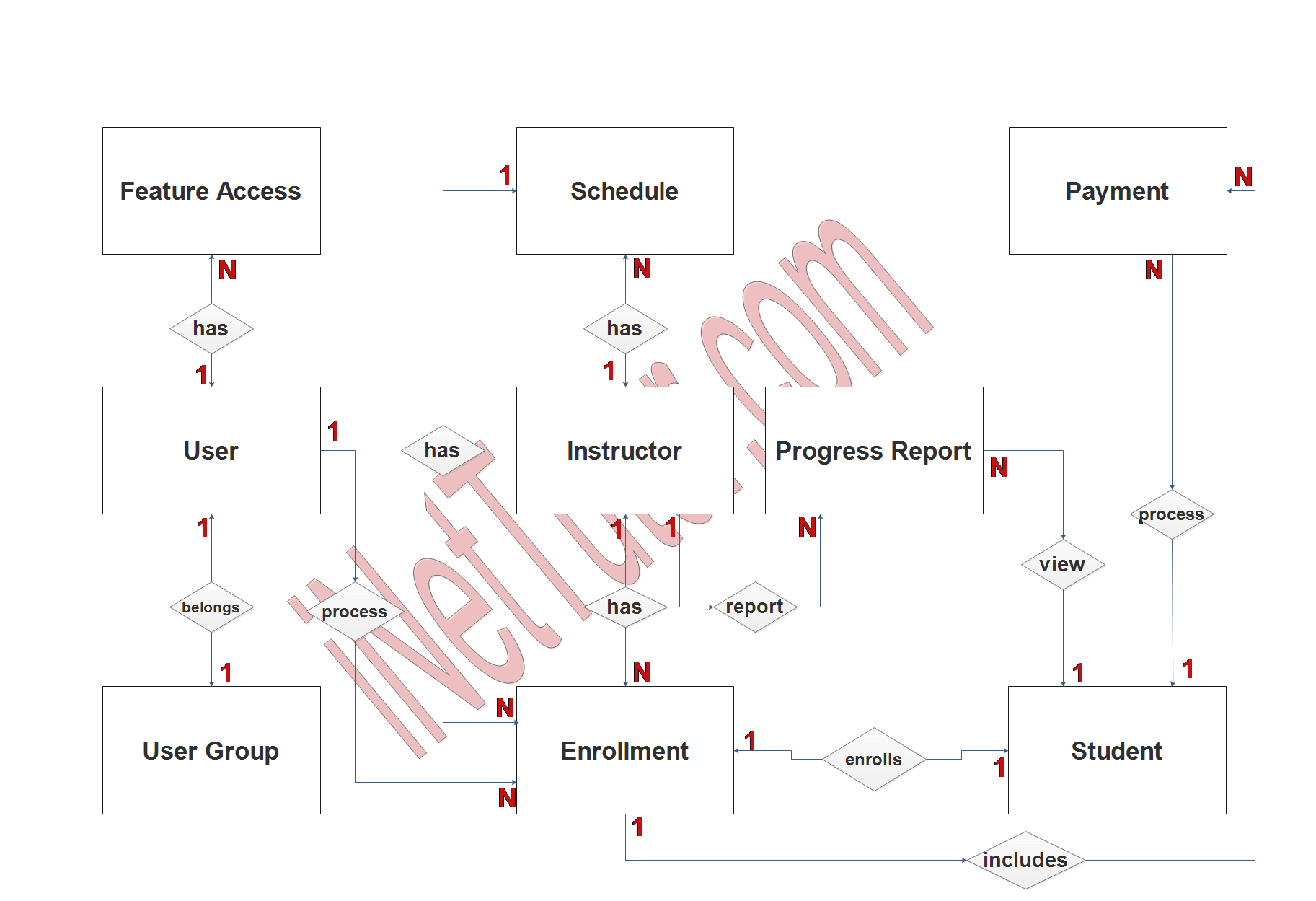
- The user belongs to a specific user group or category (1 to 1 relationship).
- The user can access 1 or more features of the system (1 to many relationship).
- The user can process multiple enrollment transactions (1 to many relationship).
- The student can only process 1 enrollment transaction at a time (1 to 1 relationship).
- The student can view their progress report several times (1 to many relationship).
- The student can process the payment several or multiple times (1 to many relationship).
- The instructor can be included in multiple enrollment or class (1 to many relationship).
- The instructor can submit multiple progress reports, depending on the class assigned to them (1 to many relationship).
- Enrollment information can be included in the payment transaction in several times (1 to many relationship).
Step 3. The last part of the ERD process is to add attributes to our entities.
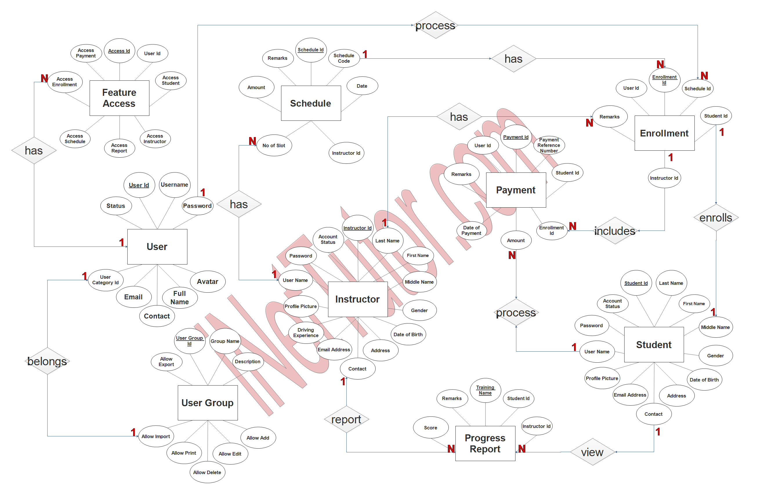
User Entity has the following attributes:
- User_ID – primary key represented with underline
- Username
- Password
- Avatar
- Fullname
- Contact
- User category ID – foreign key
- Status
User Group Entity has the following attributes:
- User Group ID – primary key represented with underline
- Group name
- Description
- Allow add
- Allow edit
- Allow delete
- Allow print
- Allow import
- Allow export
Feature Access Entity has the following attributes:
- Access ID – primary key represented with underline
- User ID – foreign key
- Access student
- Access instructor
- Access report
- Access schedule
- Access enrollment
- Access payment
Instructor Entity has the following attributes:
- Instructor ID – primary key represented with underline
- Last name
- First name
- Middle name
- Gender
- Date of birth
- Address
- Contact
- Email address
- Driving experience
- Profile picture
- Username
- Password
- Account status
Schedule Entity has the following attributes:
- Schedule ID – primary key represented with underline
- Schedule code
- Date
- Instructor ID – foreign key
- Number of slots
- Amount
- Remarks
Enrollment Entity has the following attributes:
- Enrollment ID – primary key represented with underline
- Schedule ID – foreign key
- Student ID – foreign key
- Instructor ID – foreign key
- Remarks
- User ID – foreign key
Student Entity has the following attributes:
- Student ID – primary key represented with underline
- Last name
- First name
- Middle name
- Gender
- Date of birth
- Address
- Contact
- Email address
- Profile picture
- Username
- Password
- Account status
Progress Report Entity has the following attributes:
- Training name
- Student ID – foreign key
- Instructor ID – foreign key
- Score
- remarks
Payment Entity has the following attributes:
- Payment ID – primary key represented with underline
- Payment Reference number
- Student ID – foreign key
- Enrollment ID – foreign key
- Amount
- Date of payment
- Remarks
- User ID – foreign key
Summary
An Entity Relationship diagram is a diagram that shows the different entities (tables) and how they are connected to each other, as well as how many of each type there are. eg, one to one, one to many, many to many, etc.
We hope that you have learned something about our article on how to create and prepare an ER Diagram for Driving School System. ER Diagram will serve as reference and guide for the developers to create the actual database of the project.
You may visit our Facebook page for more information, inquiries, and comments. Please subscribe also to our YouTube Channel to receive free capstone projects resources and computer programming tutorials.
Hire our team to do the project.
Related Links and Articles:
Sales and Inventory System ER Diagram
Water Refilling System ER Diagram
Dairy Farm Management System ER Diagram
Procurement Management System ER Diagram