Complaint Handling Management System ER Diagram
This article will walk you through the process of creating the entity relationship diagram (ERD) for the project Complaint Handling Management System. We will develop and describe the entity relationship diagram of the Complaint Handling Management System.
About the System
Table of Contents
The capstone project, “Complaint Handling Management System,” is a system developed to assist educational institutions in electronically handling and managing complaints. The system will improve the school’s management’s response time to complaints from kids, parents, staff, and other stakeholders.
A complaint handling management system is a process or system for receiving, documenting, and resolving customer complaints. The goal of a complaint handling management system is to ensure that customer complaints are properly addressed and resolved in a timely and satisfactory manner.
Here are the key components of a complaint handling management system:
Receiving complaints: The first step in a complaint handling management system is to establish a system for receiving customer complaints. This can include a dedicated email address, phone line, or online form for customers to submit their complaints.
Documenting complaints: Once a complaint is received, it should be documented in a central database or system to ensure that it can be tracked and managed effectively. This may include information about the customer, the nature of the complaint, and any relevant details about the issue.
Assessing complaints: After a complaint has been received and documented, it should be assessed to determine the appropriate course of action. This may involve reviewing the complaint to identify the root cause of the issue and determining whether the complaint requires further investigation or resolution.
Resolving complaints: Once a complaint has been assessed, the next step is to work to resolve it in a timely and satisfactory manner. This may involve addressing the issue directly with the customer or working with other teams or departments within the organization to find a solution.
Tracking and reporting: A complaint handling management system should also include a mechanism for tracking the status of complaints and the actions taken to resolve them. This may involve generating regular reports on the volume and types of complaints received, as well as the time it takes to resolve them.
What is an ER Diagram?
An entity-relationship (ER) diagram is a graphical representation of an organization’s data, showing the relationships between entities (such as people, places, and things) and the attributes (or characteristics) of those entities. ER diagrams are often used in database design to represent the structure of a database and the relationships between different data elements.
Let us begin with the symbols utilized in the ER Diagram.
The rectangle form represents the entity. Later on, the entity will be our database table of the Complaint Handling Management System.
The oval shape represents attribute. The columns or fields of each table in the Complaint Handling Management System will be listed here.
The diamond form represents a relationship. This will establish the associations between entities. This is often done through a primary key to foreign key relationship.
We will follow the 3 basic rules in creating the ER Diagram.
- Identify all the entities.
- Identify the relationship between entities and
- Add meaningful attributes to our entities.
Step 1 – Identify the Entities
In the Complaint Handling Management System we have the following entities:
- Department_user
- Complaint
- Stakeholder
- Course
- Department
- Complaint_details
- Admin_user
- Badwords_collection
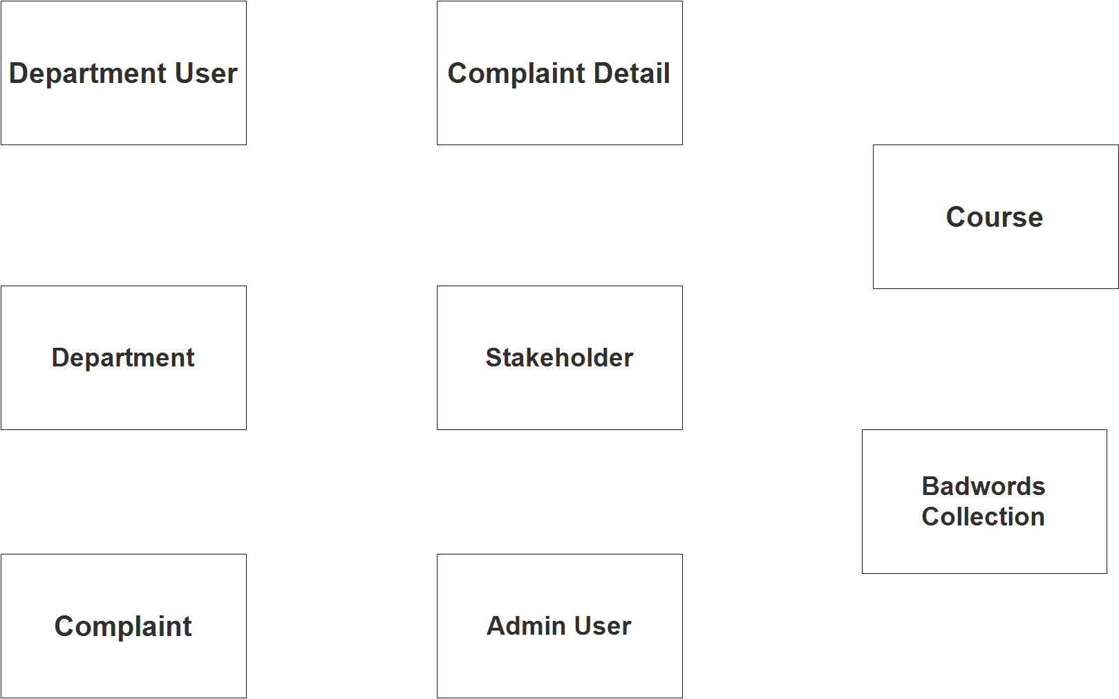
We will now draw the entities of the Complaint Handling Management System specified above and it will be represented by a rectangle shape. The image below are the entities identified in the scope of the Complaint Handling Management System.
Step 2 – Establish Relationships
After we have specified our entities, it is time now to connect or establish a relationship among the entities.
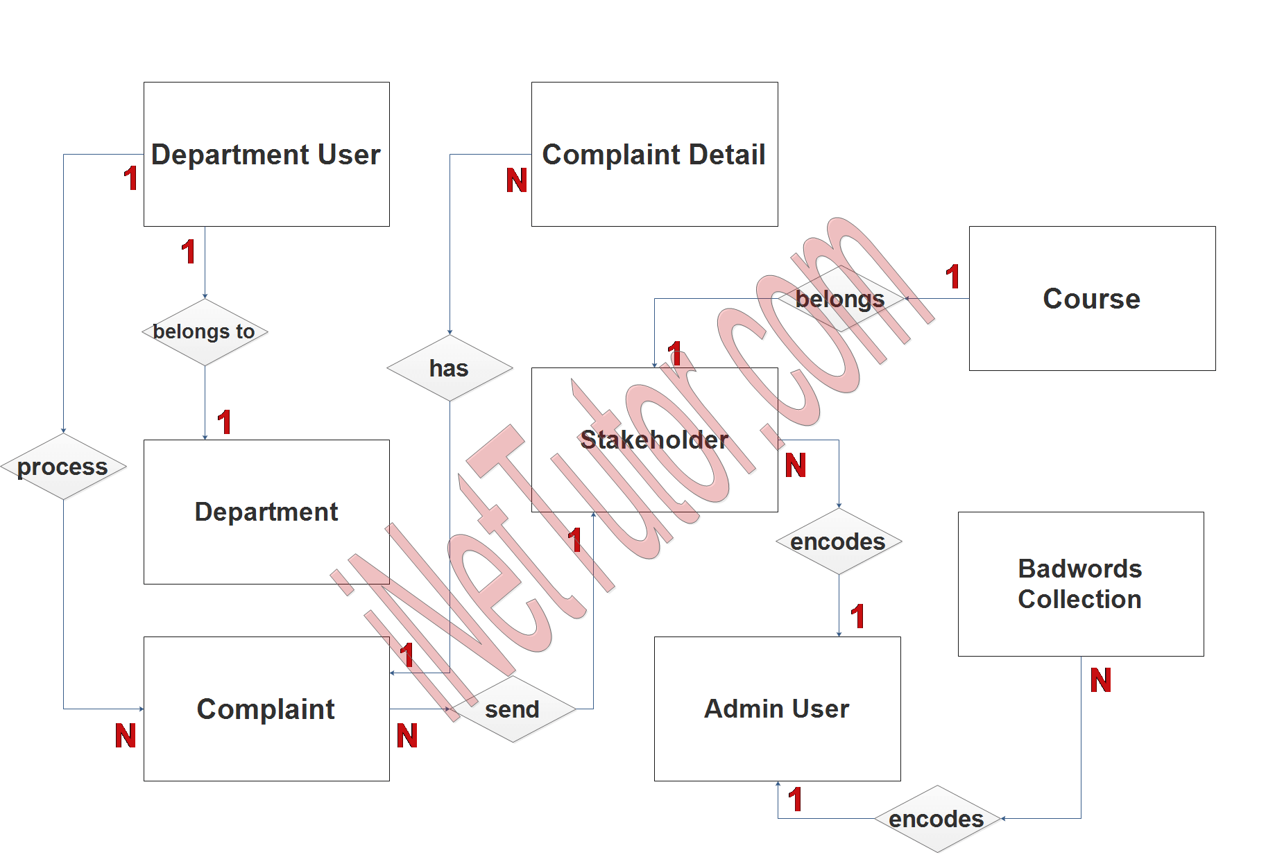
- department_id belongs to tbl_deparment.department_id (1:1). This is a one to one relationship since a department user can only be associated to a specific department.
- department_user_id process tbl_complaint.department_id (1:N). The relationship is one to many for the department user can process several complaints.
- complaint_id has tbl_complaint_details.complaint_id (1:N). A complaint needs to be specific in order to resolve quickly, thus a one to many relationship is established.
- stakeholder_id send tbl_complaint.stakeholder_id (1:N). A member or stakeholder can send multiple complaints to the system.
- course_id belongs tbl_course.course_id (1:1). The stakeholders of the system refer to the students, alumni and parents. With this, the stakeholder can only be a part of a course or department.
- user_id encodes tbl_stakeholder.admin_id (1:N). System users are the ones who processed the user registration of the stakeholders. The relationship is one to many for the system user can process multiple stakeholders profile.
- admin_user_id encodes tbl_badwords_collection.admin_id (1:N). System users manages the bad words collection that the system will automatically filter in the conversations and messages forwarded by the users.
Step 3 – Add Meaningful Attributes
The last part of the ERD process is to add attributes to our entities.
Department User entity has the following attributes:
- Department User ID – primary key
- Last name
- First name
- Middle name
- Department ID
- Contact
- Username
- Password
- Account status
Complaint entity has the following attributes:
- Complaint ID – primary key
- Complaint code
- Stakeholder ID – foreign key
- Department ID – foreign key
- Concern
- Complaint name
- Complaint details
- Attachment
- Timestamp
- Status
Stakeholder entity has the following attributes:
- Stakeholder ID – primary key
- Last name
- First name
- Middle name
- Course ID – foreign key
- Stakeholder type
- Contact
- Username
- Password
- Account status
- Admin ID – foreign key
Course entity has the following attributes:
- Course ID – primary key
- Course code
- Course name
Department entity has the following attributes:
- Department ID – primary key
- Department code
- Department name
Complaint details entity has the following attributes:
- Complaint detail ID – primary key
- Complaint ID – foreign key
- Complaint code
- Complete name
- Update message
- Date processed
- Reply from student
- Status
Admin user entity has the following attributes:
- Admin user ID – primary key
- Last name
- First name
- Middle name
- Designation
- Contact
- Username
- Password
- Account status
Badwords collection entity has the following attributes:
- Bad word ID – primary key
- Bad word
- Admin ID – foreign key
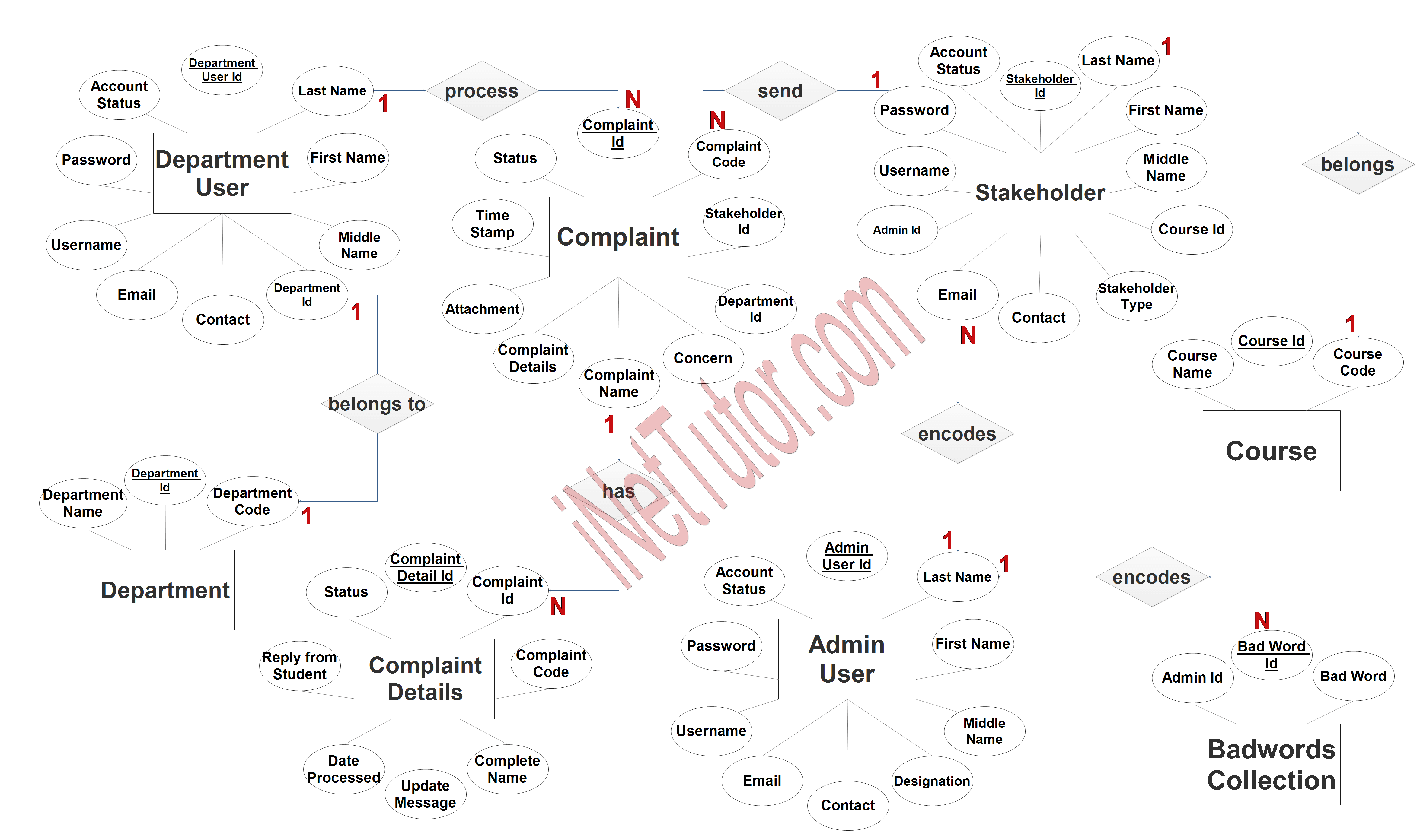
All characteristics with an underline represent the object or table’s primary key.
Summary
ER diagrams are useful for visualizing and organizing data and can help organizations to better understand the structure and relationships within their data. They can also be used to communicate data requirements and design decisions to stakeholders and developers. By implementing a complaint handling management system, organizations can better manage customer complaints, improve customer satisfaction, and identify opportunities for process improvement. Prior to the development of the project, crafting of ER Diagram will serve as guide and blueprint for the next stage which is the database design.
The next stage is to transform the ER Diagram plan into an actual database; please look at the Complaints Handling Management System article that was previously posted.
For a soft copy of the Complaint Handling Management System, please contact us via our Facebook page.
Readers are also interested in:
Complaint Management System Free Template in PHP and Bootstrap
Complaints Handling Management System Database Design
You may visit our Facebook page for more information, inquiries, and comments. Please subscribe also to our YouTube Channel to receive free capstone projects resources and computer programming tutorials.
Hire our team to do the project.