Barangay Management System ER Diagram
This article will discuss the step by step process on how to prepare the entity relationship diagram or ERD of the project entitled Barangay Management System.
The capstone project entitled Barangay Management System is available in two flavors; 1 is good for local area network, this version will work in an offline setting, 2 is the online version written in PHP and MySQL. The core feature includes the resident profiling, blotter report and certificate issuance.
The first step in the development of the Barangay Management System is to prepare the ER diagram that will serve as the basis later on in the creation of the actual database.
We will create and explain the process of making the entity relationship diagram of Barangay Management System.
Let’s start from the symbols used in the ER Diagram.
Entity is represented by the rectangle shape. The entity will be our database table of Barangay Management System later on.
Attribute is represented by the oval shape. This will be the columns or fields of each table in the Barangay Management System.
Relationship is represented by diamond shape. This will determine the relationships among entities. This is usually in a form of primary key to foreign key connection.
We will follow the 3 basic rules in creating the ER Diagram.
- Identify all the entities.
- Identify the relationship between entities and
- Add meaningful attributes to our entities.
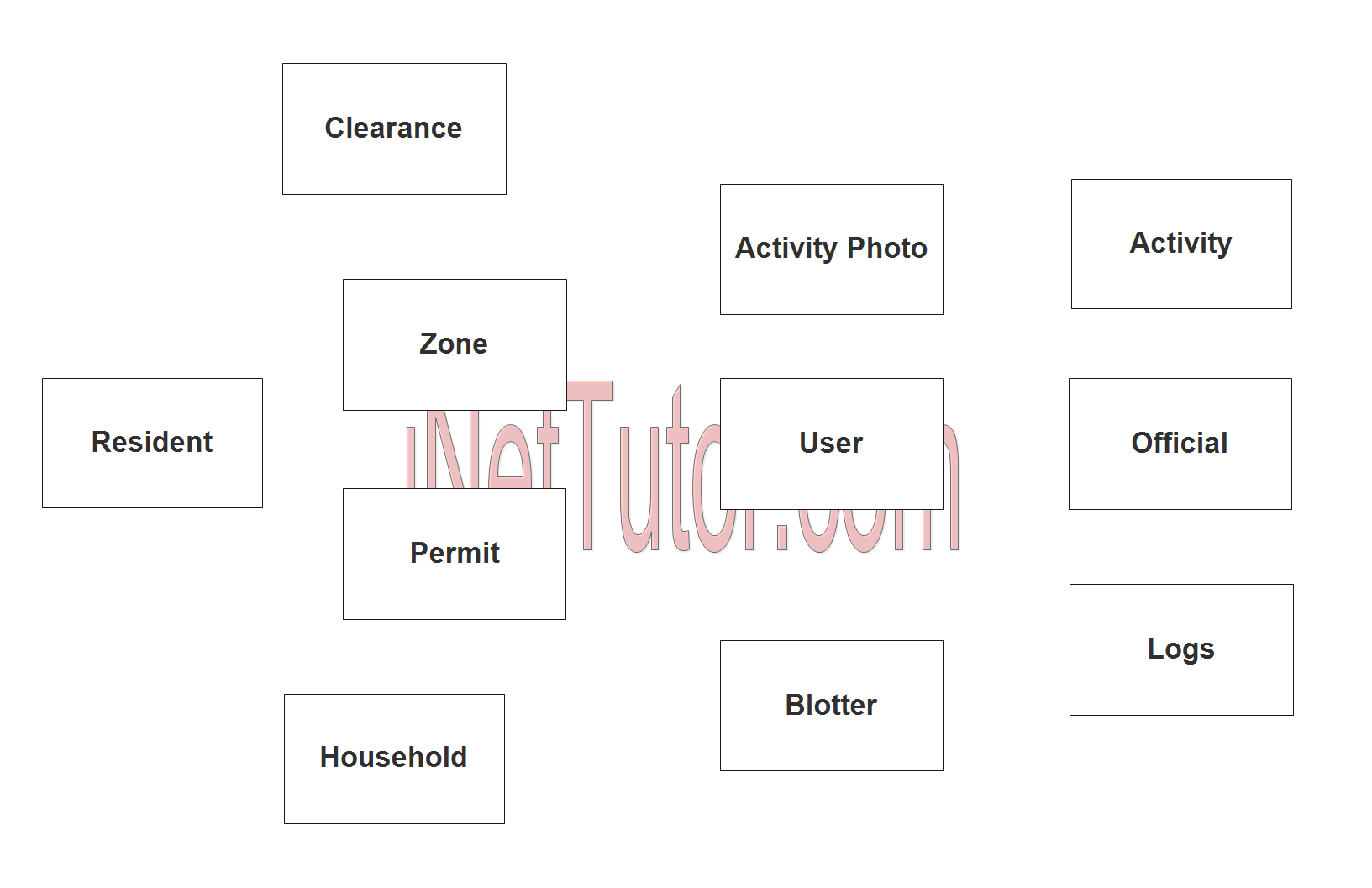
Step 1. In the Barangay Management System we have the following entities
- User
- Logs
- Resident
- Clearance
- Zone
- Permit
- Household
- Activity
- Activity Photo
- Blotter
- Official
Our design of Barangay Management System consists of 11 entities; the specified entities will be our database tables in the design and implementation of Barangay Management database schema.
We will now draw the entities of the Barangay Management System specified above and it will be represented by a rectangle shape. The image below is the entities identified in the scope of the Barangay Management System.
Step 2. After we have specified our entities, it is time now to connect or establish a relationship among the entities.
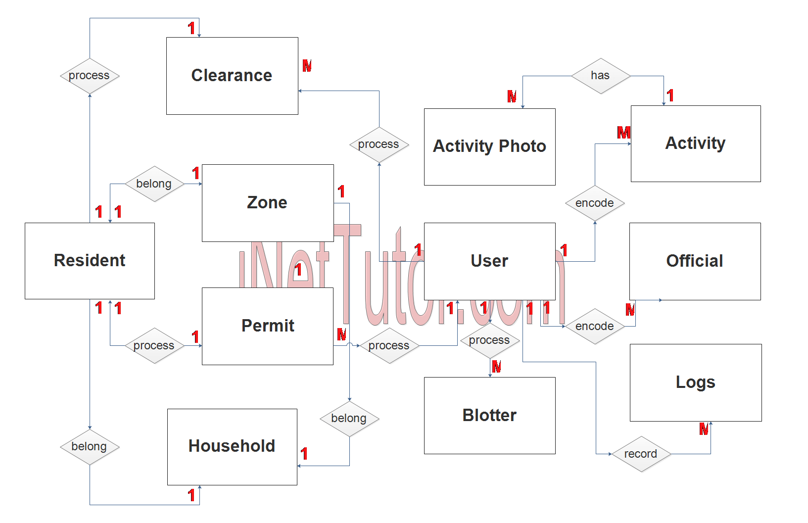
- The user encodes the barangay officials (1 to many relationship).
- The user encodes the barangay activities for the entire year (1 to many relationship).
- The activity contains photos or images (1 to many relationship).
- The user processes the blotter reports (1 to many relationship).
- The user processes the permit requests by the resident (1 to many relationship).
- The user processes and prints the clearances of residents (1 to many relationship).
- The system records the activity of the user (1 to many relationship).
- The resident belongs to a specific zone or purok (1 to 1 relationship).
- The resident belongs to a specific household (1 to 1 relationship).
- The household is recorded in a zone (1 to 1 relationship).
- The resident can only process 1 clearance at a time (1 to 1 relationship).
- The resident can only process 1 permit at a time (1 to 1 relationship).
Step 3. The last part of the ERD process is to add attributes to our entities.
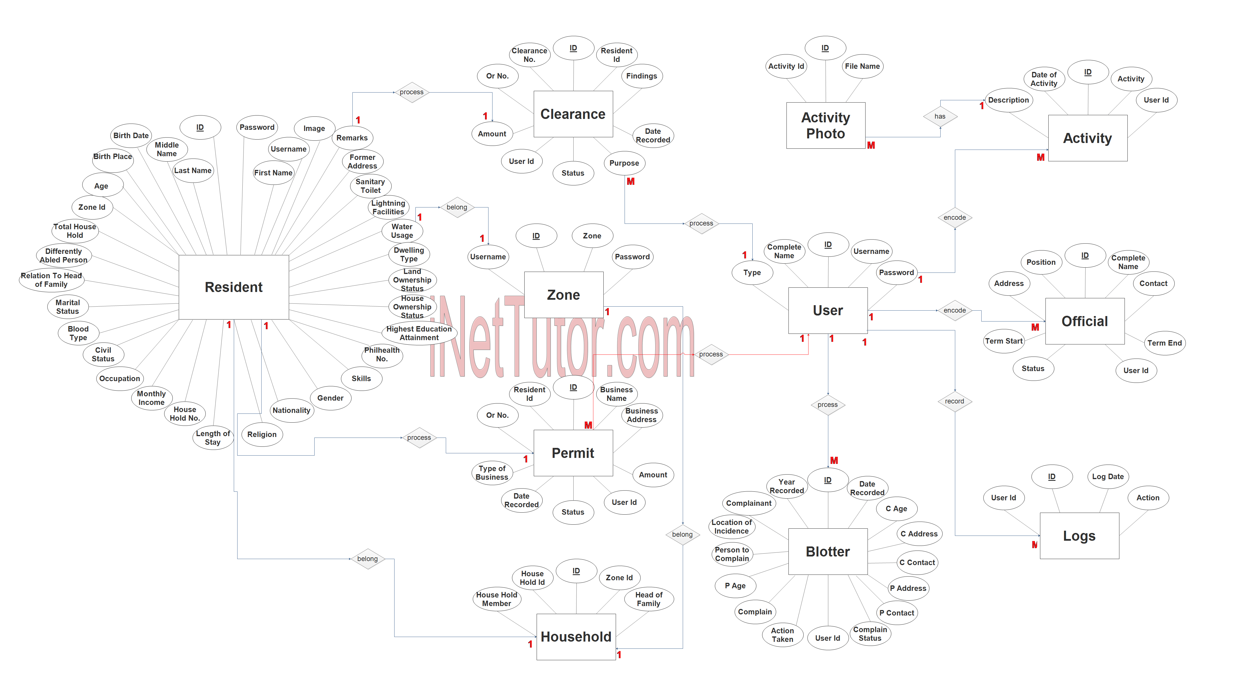
User Entity has the following attributes:
- ID – primary key represented with underline
- Complete Name
- Username
- Password
- Type
Logs Entity has the following attributes:
- ID – primary key represented with underline
- User ID – foreign key
- Log Date
- Action
Resident Entity has the following attributes:
- ID – primary key represented with underline
- First name
- Last name
- Middle name
- Birthdate
- Birth place
- Age
- Zone ID – foreign key
- Total Household
- Differently abled person
- Related to head of family
- Marital Status
- Blood type
- Civil Status
- Occupation
- Monthly Income
- Household no
- Length of stay
- Religion
- Nationality
- Gender
- Skills
- Philhealth no
- Highest Educational Attainment
- House ownership status
- Land ownership status
- Dwelling type
- Water usage
- Lightning facilities
- Sanitary toilet
- Former address
- Remarks
- Image
- Username
- password
Clearance Entity has the following attributes:
- ID – primary key represented with underline
- Resident ID – foreign key
- Clearance no
- OR no
- Amount
- User ID – foreign key
- Status
- Purpose
- Findings
- Date recorded
Zone Entity has the following attributes:
- ID – primary key represented with underline
- Zone
- Username
- Password
Permit Entity has the following attributes:
- ID – primary key represented with underline
- Resident ID – foreign key
- Business name
- Business Address
- Type of business
- Date recorded
- Status
- OR No
- Amount
- User ID – foreign key
Household Entity has the following attributes:
- ID – primary key represented with underline
- Zone ID – foreign key
- Household ID – foreign key
- Household member
- Head of Family
Activity Entity has the following attributes:
- ID – primary key represented with underline
- Activity
- Date of Activity
- Description
- User ID – foreign key
Activity Photo Entity has the following attributes:
- ID – primary key represented with underline
- Activity ID – foreign key
- Filename
Blotter Entity has the following attributes:
- ID – primary key represented with underline
- Year Recorded
- Date Recorded
- Complainant
- Location of Incidence
- Person to complain
- Complain
- Action take
- Complain status
- User ID – foreign key
Official Entity has the following attributes:
- ID – primary key represented with underline
- Complete name
- Contact
- Position
- Address
- Term start
- Term end
- Status
- User ID – foreign key
Note: all attributes with underline represents the primary key of the entity or table.
The next step is to convert the plan designed on ER Diagram into the actual database, please search for the Barangay Management System article which was already posted.
Contact us on our facebook page for the softcopy of the Barangay Management System.
You may visit our facebook page for more information, inquiries and comments.
Hire our team to do the project.