Water Billing System Entity Relationship Diagram
Introduction
Table of Contents
A water billing system is critical for managing water utility services, ensuring accurate billing, and tracking consumption for residential and commercial users. Effective data management in this domain supports operational efficiency and customer satisfaction. An Entity Relationship Diagram (ERD) is a visual tool used to design databases by mapping entities, their attributes, and relationships. In a water billing system, an ERD outlines how customers, meters, bills, and payments interact, providing a blueprint for developers to build robust databases.
This post aims to guide readers through understanding and creating an ERD for a water billing system. Whether you’re a database designer, developer, or student learning database concepts, this guide offers clear steps and practical insights. By exploring the water billing domain, we’ll demonstrate how ERDs address data organization challenges, such as tracking usage or handling payment disputes. The post will walk you through key ERD concepts, a step-by-step design process, and a PlantUML script to visualize the system. With real-world applications and best practices, you’ll gain the knowledge to model efficient databases for water utilities and beyond.
Overview of the Water Billing System
A water billing system manages the processes of tracking water usage, generating bills, and processing payments. Key components include customers, water meters, billing records, and payment transactions. Customers are individuals or businesses receiving water services, while meters measure consumption. Bills are generated based on usage rates, and payments are recorded to settle accounts. Additional elements, like tariffs or penalties for late payments, may also be included.
Data management challenges in this domain include ensuring accurate meter readings, handling large volumes of customer data, and maintaining billing transparency. Errors in usage tracking or payment processing can lead to disputes or revenue loss. An ERD helps by organizing data into structured entities and defining clear relationships, such as linking a customer to their meter or a bill to a payment.
For example, consider a small municipal water utility serving 1,000 households. The system must record each customer’s details, monitor monthly usage, calculate bills based on tiered rates, and track payments. An ERD simplifies this by visually representing how data flows between entities, ensuring the database is scalable and efficient. By addressing these challenges, ERDs enable utilities to streamline operations and improve service delivery.
Key Concepts of ER Diagrams
An Entity Relationship Diagram (ERD) is a visual representation of a database’s structure, consisting of entities, attributes, relationships, and keys. Entities are objects like Customer or Bill in a water billing system. Attributes describe entities (e.g., Customer: ID, Name, Address). Relationships define how entities interact, such as a Customer OWNS a Meter. Primary keys (unique identifiers, e.g., CustomerID) and foreign keys (linking entities, e.g., Meter’s CustomerID) ensure data integrity.
In a water billing system, entities like Customer, Meter, Bill, and Payment are central. For instance, a Customer entity might have attributes like CustomerID (primary key), Name, and Phone. A Bill entity could include BillID (primary key), Amount, and IssueDate. Relationships, such as a Customer RECEIVES a Bill, are depicted with lines and cardinality (e.g., one-to-many, where one customer can have multiple bills). These concepts ensure the database captures the system’s complexity without redundancy.
Below is a simple example of a Customer entity in an ERD:
[Customer]
- CustomerID (Primary Key)
- Name
- Address
- Phone
This entity connects to others, like Meter, through relationships. Understanding these fundamentals helps database designers create ERDs that accurately model the water billing system, ensuring efficient data storage and retrieval.
Designing the ER Diagram for a Water Billing System
Creating an ER Diagram for a water billing system involves four steps: identifying entities, defining attributes, establishing relationships, and specifying constraints. Here’s how to design one:
Step 1: Identify Entities The main entities in a water billing system are:
- Customer: Represents individuals or businesses using water services.
- Meter: Tracks water consumption for each customer.
- Bill: Records billing details based on usage.
- Payment: Captures payment transactions for bills.
Step 2: Define Attributes Each entity has specific attributes:
- Customer: CustomerID (primary key), Name, Address, Phone, Email.
- Meter: MeterID (primary key), CustomerID (foreign key), InstallationDate, Status.
- Bill: BillID (primary key), CustomerID (foreign key), MeterID (foreign key), Amount, IssueDate, DueDate.
- Payment: PaymentID (primary key), BillID (foreign key), Amount, PaymentDate, Method.
Step 3: Establish Relationships Relationships define how entities interact:
- A Customer OWNS a Meter (one-to-many: one customer can have multiple meters, but each meter belongs to one customer).
- A Customer RECEIVES a Bill (one-to-many: one customer can have multiple bills).
- A Meter GENERATES a Bill (one-to-many: one meter can generate multiple bills).
- A Bill RECEIVES a Payment (one-to-many: one bill can have multiple payments, e.g., partial payments).
Step 4: Specify Constraints
- Primary Keys: CustomerID, MeterID, BillID, PaymentID ensure unique identification.
- Foreign Keys: CustomerID in Meter and Bill, MeterID in Bill, BillID in Payment link entities.
- Cardinality: One-to-many relationships (e.g., Customer to Bill) ensure scalability. No many-to-many relationships exist in this design, avoiding junction tables.
Textual Description The ERD includes four entities: Customer, Meter, Bill, and Payment. A Customer owns one or more Meters, which generate Bills based on usage. Bills are paid through Payments. Primary and foreign keys maintain data integrity, and one-to-many relationships ensure the structure supports real-world processes.
ER Diagram Example
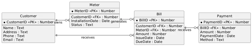
Below is a conceptual ER Diagram for a water billing system, created using a tool like Draw.io. It includes four entities: Customer, Meter, Bill, and Payment.
- Customer: Attributes include CustomerID (primary key), Name, Address, Phone, Email. It connects to Meter and Bill.
- Meter: Attributes are MeterID (primary key), CustomerID (foreign key), InstallationDate, Status. It links to Customer and Bill.
- Bill: Attributes include BillID (primary key), CustomerID (foreign key), MeterID (foreign key), Amount, IssueDate, DueDate. It connects to Customer, Meter, and Payment.
- Payment: Attributes are PaymentID (primary key), BillID (foreign key), Amount, PaymentDate, Method. It links to Bill.
Relationships:
- Customer OWNS Meter (one-to-many).
- Customer RECEIVES Bill (one-to-many).
- Meter GENERATES Bill (one-to-many).
- Bill RECEIVES Payment (one-to-many).
A domain-specific nuance is tracking partial payments, where a bill may have multiple payment records. This ERD ensures accurate billing and payment reconciliation for water utilities.
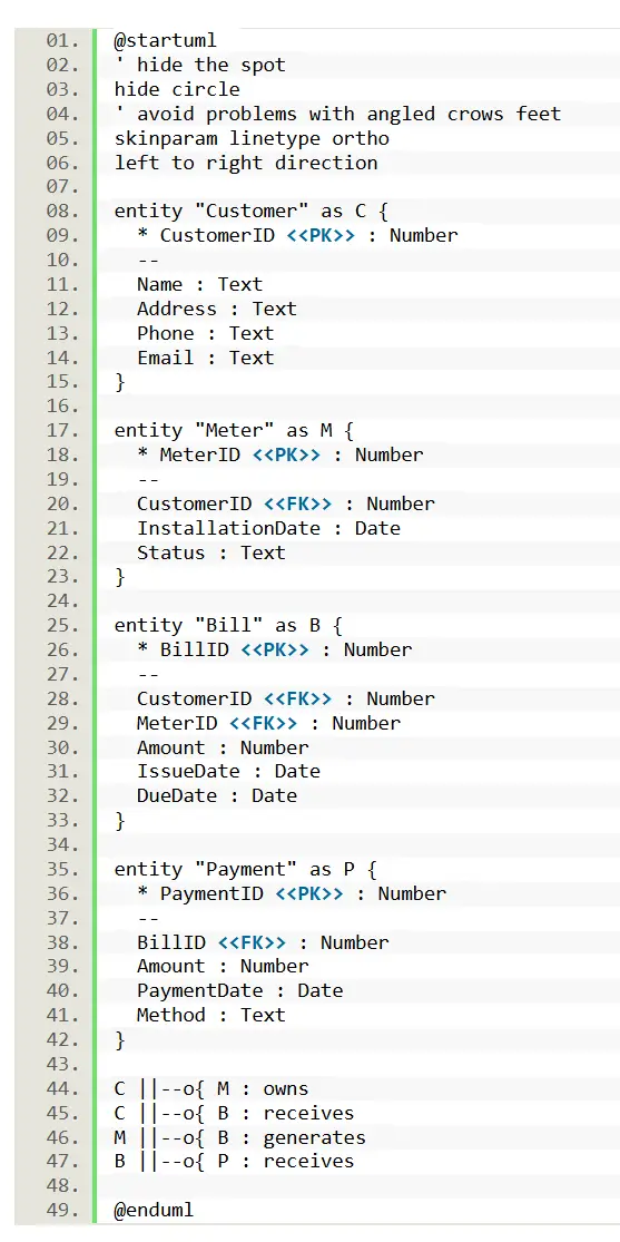
PlantUML Script for Water Billing System ERD
@startuml
' hide the spot
hide circle
' avoid problems with angled crows feet
skinparam linetype ortho
left to right direction

entity "Customer" as C {
* CustomerID <<PK>> : Number
--
Name : Text
Address : Text
Phone : Text
Email : Text
}

entity "Meter" as M {
* MeterID <<PK>> : Number
--
CustomerID <<FK>> : Number
InstallationDate : Date
Status : Text
}

entity "Bill" as B {
* BillID <<PK>> : Number
--
CustomerID <<FK>> : Number
MeterID <<FK>> : Number
Amount : Number
IssueDate : Date
DueDate : Date
}

entity "Payment" as P {
* PaymentID <<PK>> : Number
--
BillID <<FK>> : Number
Amount : Number
PaymentDate : Date
Method : Text
}

C ||--o{ M : owns
C ||--o{ B : receives
M ||--o{ B : generates
B ||--o{ P : receives

@enduml
This PlantUML script creates a clear ERD with no intersecting lines, using orthogonal line routing (skinparam linetype ortho). Entities are defined with primary and foreign keys, and relationships are labeled for clarity. No many-to-many relationships exist, so no junction table is needed.
Best Practices for Water Billing System ER Diagrams
Designing effective ER Diagrams for water billing systems requires attention to detail and foresight. First, normalize data to avoid redundancy—store customer details once in the Customer entity, not repeatedly in Bills or Payments. Ensure scalability by using clear primary and foreign keys to handle growing customer bases. Keep the design simple, focusing on core entities like Customer, Meter, Bill, and Payment, and avoid overcomplicating relationships, such as unnecessary links between Payments and Meters.
Use consistent naming conventions (e.g., CustomerID across entities) for clarity. Validate cardinality to reflect real-world constraints, like one Meter generating multiple Bills. Test the ERD against edge cases, such as handling inactive meters or disputed bills. Tools like MySQL Workbench, Lucidchart, or Draw.io are excellent for creating and visualizing ERDs, offering templates and export options.
Common pitfalls include overlooking partial payments or failing to account for tariff changes, which can disrupt billing accuracy. Regularly review the ERD during development to ensure it aligns with system requirements. By following these practices, you’ll create a robust ERD that supports efficient data management for water billing systems.
Real-World Applications
An ER Diagram for a water billing system translates into a functional database for utility companies, powering billing software and customer portals. For example, the ERD supports systems like those used by municipal water departments, enabling accurate usage tracking, bill generation, and payment processing. Industries like water utilities, smart city infrastructure, and environmental management rely on such diagrams to ensure data integrity.
Tools like SAP Utilities or Oracle Utilities Customer Care and Billing implement similar database structures, using ERDs to model complex billing workflows. In practice, the ERD ensures seamless integration with meter-reading devices and online payment gateways. For instance, a city utility serving thousands of households uses the ERD to manage customer data, prevent billing errors, and streamline operations. By providing a clear data model, the ERD supports real-world applications that enhance service delivery and operational efficiency.
Conclusion
This guide explored how to design an Entity Relationship Diagram for a water billing system, simplifying data modeling for utility management. By identifying entities like Customer, Meter, Bill, and Payment, defining their attributes, and establishing relationships, you can create a robust ERD that ensures accurate billing and efficient data management. Key takeaways include the importance of normalization, clear constraints, and scalable design to address real-world challenges like payment tracking or usage disputes.
Readers are encouraged to try creating their own ERD using tools like Draw.io or MySQL Workbench, or explore related domains like electricity billing. Share your feedback in the comments, check out our next post on database optimization, or visit resources like PlantUML’s documentation for more. With this knowledge, you’re equipped to build effective database models for water utilities and beyond, enhancing operational efficiency and customer satisfaction.
You may visit our Facebook page for more information, inquiries, and comments. Please subscribe also to our YouTube Channel to receive free capstone projects resources and computer programming tutorials.
Hire our team to do the project.