Records Management DFD, ERD and Decomposition Chart
Design of Software, Systems, Product and Processes
Design phase describes desired features and operations in detail, including screen layouts, and other documentation.
In this phase, the physical system of the software was developed. The researchers established the overall system architecture such as the layout/features, system design and other content element which is required in supporting the system.
The design of the developed system helps in specifying hardware and system requirements, helps in defining the overall system architecture and meets the requirements both software and hardware.
The design of software describes the desired features and operations in detail, including screen layouts, and other documentation. Also the full functions of every button which intended to accomplish goals of the system.
After designing the overall design of the system, the researchers had produced graphical representation of the flow of data through an information system, modeling its process aspects known as Data Flow Diagram (DFD) Levels that shows what kinds of information will be input to and output from the system, where the data will come from and go to, and where the data will be stored.
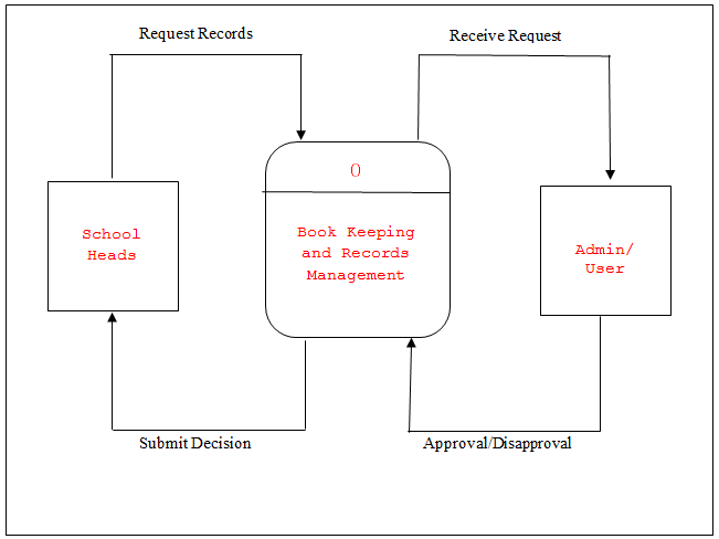
Figure 1.0 Shows the Context Diagram
This diagram shows the overview and the scope of the system in which the school heads and admin/user can access only the system. The school heads request records through sending message and manual request that are directly stored to the system. The Admin/User can read the received requests in the system from the different schools that requested and the one who approved and disapproved. The Records Management will generate the entire request and submit the decision.
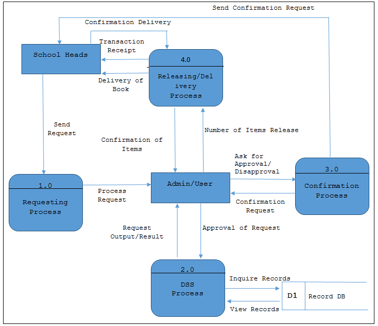
Figure 2.0 Shows the DFD Level 0
This diagram represents the Records Management major process, data flows, entities and data stores. The school heads first request for book by sending message or manual way of requesting to the system. The message will be stored in the system and will pass in the DSS Process for the calculation of the books percentage to be distributed in every school. Using the DSS, there will be an equal amount of books to be delivered to different schools that requested. The DSS will inquire records to the Records DB and give the request result to the Admin. The Admin will ask for book request confirmation. After the confirmation process, the Admin will allow releasing of records to the schools that requested. The personnel who delivered books will provide transaction receipt for delivery confirmation.
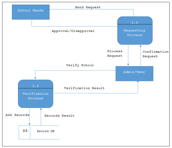
Figure 3.0 Shows the Level 1 DFD
Data Flow Diagram (DFD) Level 1 shows the requesting process of every school heads requests via sending messages to the Records Management and manual way of requesting. The Admin/User are the responsible to confirmed requests and then verification process for schools if that schools are in the system’s database.
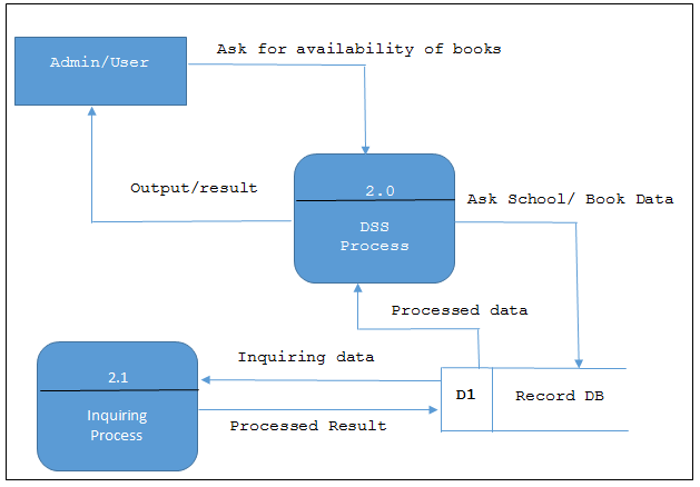
Figure 4.0 Shows the Level 2 DFD
Data Flow Diagram Level 2 shows the DSS Process where it processed school/book records by inquiring data from the database. The DSS process will calculate the book percentage to be distributed to the schools that requested to have an equal released of records. In this level, the Admin/User will ask first the availability of books to the DSS and the DSS Process display the result/output.
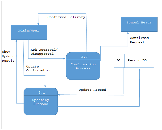
Figure 5.0 Shows the Level 3 DFD
Data Flow Diagram Level 3 shows the confirmation process for approval/disapproval of school requests. The Admin/User will approve the request after updating the records from the database. The confirmation process will send confirmation message to school heads.
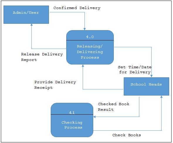
Figure 6.0 Shows the Level 4 DFD
Data Flow Diagram Level 4 shows the delivering and releasing process of the records to be distributed in every school that requested after the confirmation. This process will inform the school heads of the time and date for book delivery. If the books were already delivered, the checking process will be done by the school heads where they need to check the number of books and submit the result and provide receipt of delivery.
Entity-Relationship Diagram (ERD) – is a data modeling technique that graphically illustrates an information system’s entities and the relationships between those entities. An ERD is a conceptual and representational model of data used to represent the entity framework infrastructure.
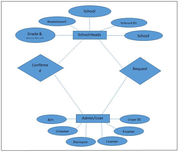
Figure 7.0 Shows the Entity Relationship
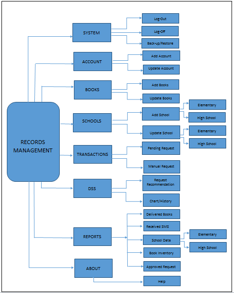
Figure 8.0 Shows the Decomposition Chart
This figure represents the Decomposition Chart or the Software Design and Process of Record Management. It shows different main menus and contains sub-menus.
Development and Testing
During this phase, systems are developed or acquired based on detailed design specifications. The system is validated through a sequence of unit, integration, performance, system, and acceptance testing. The objective is to ensure that the system functions as expected and that client’s requirements are satisfied. All system components, applications, procedures, and associated documentation are developed / acquired, tested, and integrated. This phase requires strong user participation in order to verify thorough testing of all requirements and to meet all business needs.
During the system development, the software is designed and produced, while attempting to accomplish all of the requirements and design documents that were set forth within the previous stage which is the design phase and transform them into an actual system.
In the testing phase, the researchers determine whether the quality of the product or service meets the specified requirements in the analysis phase and finds any errors present in the code. Software testing can also provide an objective, independent view of the software to allow the clients to appreciate and understand the risks of software implementation. Test techniques include, but are not limited to the process of executing a program or application with the intent of finding software bugs (errors or other defects) where the system was checked if all the modules/units coordinate with each other and the system behaves as per the specifications. It used different ways to determine if the system is capable and meets the need of the client by testing its functionality; this is referred to Initial and Final Testing where a number of testing tools and methods are used for testing purpose which includes the McCall’s Software Quality Model in evaluating the system’s functionality and design.
Credits to the authors of the project.
You may visit our facebook page for more information, inquiries and comments.
Hire our team to do the project.