Fire Safety Inspection Certificate System ER Diagram
The capstone project entitled Fire Safety Inspection Certificate System is an online platform to cater the transactions and records management of certificate issuance for fire safety. The platform is intended to automate the application process as well as the inspection monitoring and payment system. PHP, MySQL and Bootstrap were used for the development of the project
You may visit and read the articles posted in relation to Fire Safety Inspection Certificate System
- Fire Inspection Information System Chapter 1
- Fire Safety Inspection Certificate System Database Model
This article will discuss the step by step process on how to prepare the entity relationship diagram or ERD of the project entitled Fire Safety Inspection Certificate System.
The first step in the development of the Fire Safety Inspection Certificate System is to prepare the ER diagram that will serve as the basis later on in the creation of the actual database.
We will create and explain the process of making the entity relationship diagram of Fire Safety Inspection Certificate System.
Let’s start from the symbols used in the ER Diagram.
Entity is represented by the rectangle shape. The entity will be our database table of Fire Safety Inspection Certificate System later on.
Attribute is represented by the oval shape. This will be the columns or fields of each table in the Fire Safety Inspection Certificate System.
Relationship is represented by diamond shape. This will determine the relationships among entities. This is usually in a form of primary key to foreign key connection.
We will follow the 3 basic rules in creating the ER Diagram.
- Identify all the entities.
- Identify the relationship between entities and
- Add meaningful attributes to our entities.
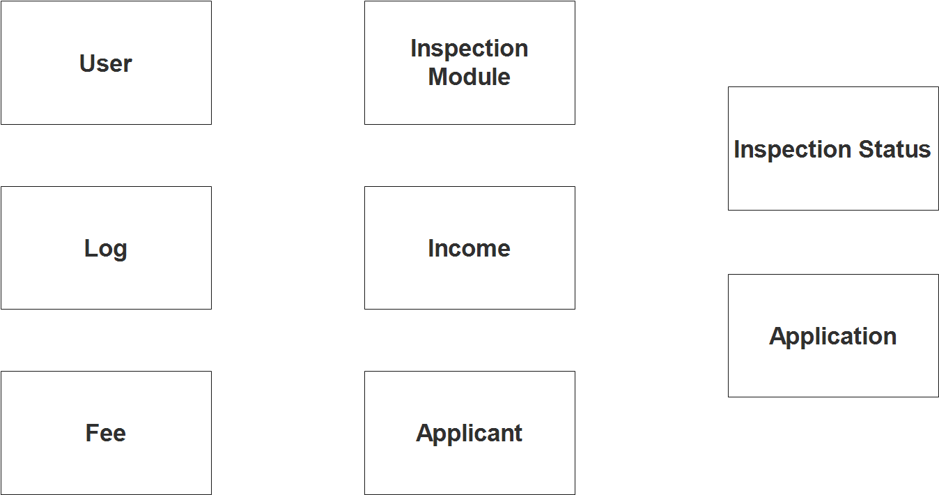
Step 1. In the Fire Safety Inspection Certificate System we have the following entities
- User
- Log
- Fee
- Inspection Module
- Income
- Applicant
- Inspection Status
- Application
Our design of Fire Safety Inspection Certificate System consists of 8 entities; the specified entities will be our database tables in the design and implementation of Fire Safety Inspection System database schema.
We will now draw the entities of the Fire Safety Inspection Certificate System specified above and it will be represented by a rectangle shape. The image below is the entities identified in the scope of the Fire Safety Inspection Certificate System.
Step 2. After we have specified our entities, it is time now to connect or establish a relationship among the entities.
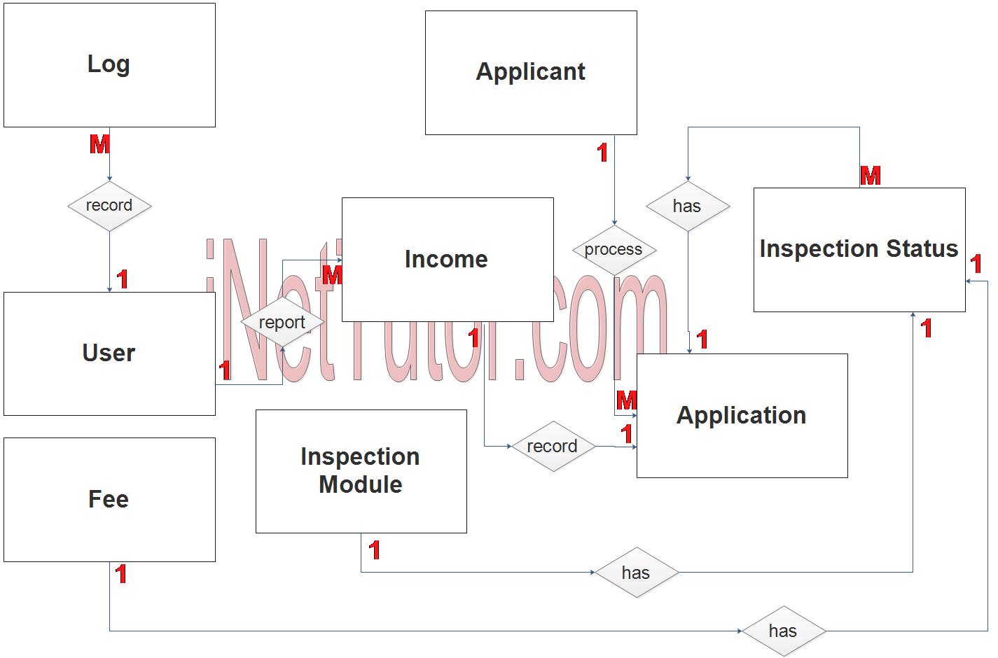
- Activities of the user conducted in the system will be stored in the log table (1 to many relationship).
- The user can print-out the income report (1 to many relationship). It was labeled as 1 to many since the user can print the report multiple times.
- The applicant can apply and process for multiple application (1 to many relationship). It means that the applicant has 1 or more businesses under his name or management.
- The application has multiple inspection criteria (1 to many relationship).
- Every inspection contains a specific requirement to accomplished (1 to 1 relationship).
- Every criterion has a corresponding payment amount or fee (1 to 1 relationship).
- The total application amount will be included in the income report (1 to 1 relationship).
Step 3. The last part of the ERD process is to add attributes to our entities.
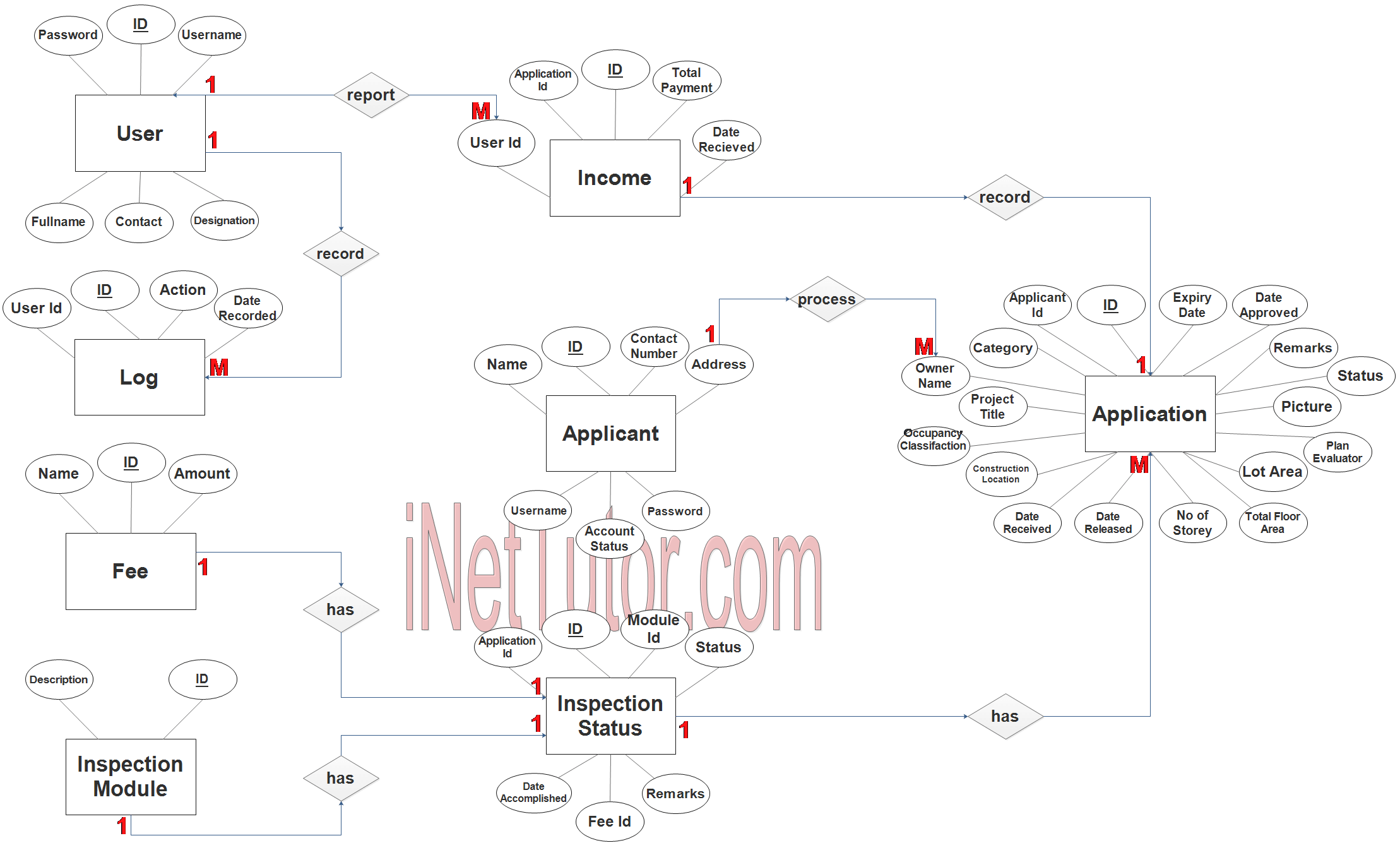
User Entity has the following attributes:
- ID – primary key represented with underline
- Full name
- Contact
- Designation
- Username
- password
Log Entity has the following attributes:
- ID – primary key represented with underline
- User ID – foreign key
- Action
- Date Recorded
Fee Entity has the following attributes:
- ID – primary key represented with underline
- Name
- Amount
Inspection Module Entity has the following attributes:
- ID – primary key represented with underline
- Description
Income Entity has the following attributes:
- ID – primary key represented with underline
- Application ID – foreign key
- User ID – foreign key
- Total Payment
- Date Received
Applicant Entity has the following attributes:
- ID – primary key represented with underline
- Name
- Contact Number
- Address
- Username
- Password
- Account Status
Inspection Status Entity has the following attributes:
- ID – primary key represented with underline
- Module ID – foreign key
- Application ID – foreign key
- Status
- Fee ID – foreign key
- Remarks
- Date Accomplished
Application Entity has the following attributes:
- ID – primary key represented with underline
- Applicant ID
- Category
- Owner Name
- Project Title
- Occupancy Classification
- Construction Location
- Date Received
- Date Released
- No of Storey
- Total Floor area
- Lot area
- Plan evaluator
- Picture
- Expiry date
- Date approved
- Status remarks
Note: all attributes with underline represents the primary key of the entity or table.
The next step is to convert the plan designed on ER Diagram into the actual database, please search for the Fire Safety Inspection Certificate System article which was already posted.
Contact us on our facebook page for the softcopy of the Fire Safety Inspection Certificate System.
You may visit our facebook page for more information, inquiries and comments.
Hire our team to do the project.