Customer Satisfaction System ER Diagram
This article will discuss the step by step process on how to prepare the entity relationship diagram or ERD of the project entitled Customer Satisfaction System.
Customer Satisfaction System is a survey type database oriented system that can be implemented in local setup or can be deployed online. It has two parts; the first part is for the customers, clients and students, they can use their smartphone and tables and can rate a certain service. The second part is for the administrators to view, archive and generate report on the ratings submitted by the customers.
The purpose of the study is to improve, develop, and implement the proposed system that will help the organization in developing Customer Satisfaction Survey. It presents a new aspect of developing the study including on the different services. Through using Tablets to survey, it can make the company or organization effective and efficient with the use of this technology.
The first step in the development of the Customer Satisfaction System is to prepare the ER diagram that will serve as the basis later on in the creation of the actual database.
We will create and explain the process of making the entity relationship diagram of customer satisfaction system.
Let’s start from the symbols used in the ER Diagram.
Entity is represented by the rectangle shape. The entity will be our database table of Customer Satisfaction System later on.
Attribute is represented by the oval shape. This will be the columns or fields of each table in the Customer Satisfaction System.
Relationship is represented by diamond shape. This will determine the relationships among entities. This is usually in a form of primary key to foreign key connection.
We will follow the 3 basic rules in creating the ER Diagram.
- Identify all the entities.
- Identify the relationship between entities and
- Add meaningful attributes to our entities.
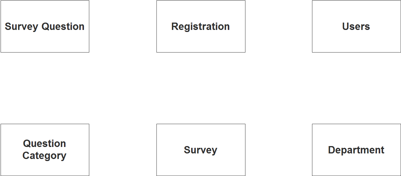
Step 1. In the Customer Satisfaction System we have the following entities
- Survey Question
- Question Category
- Survey
- Registration
- Department
- Users
We will now draw the entities of the Customer Satisfaction System specified above and it will be represented by a rectangle shape. The image below is the entities identified in the scope of the Customer Satisfaction System.
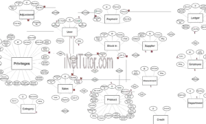
Step 2. After we have specified our entities, it is time now to connect or establish a relationship among the entities.
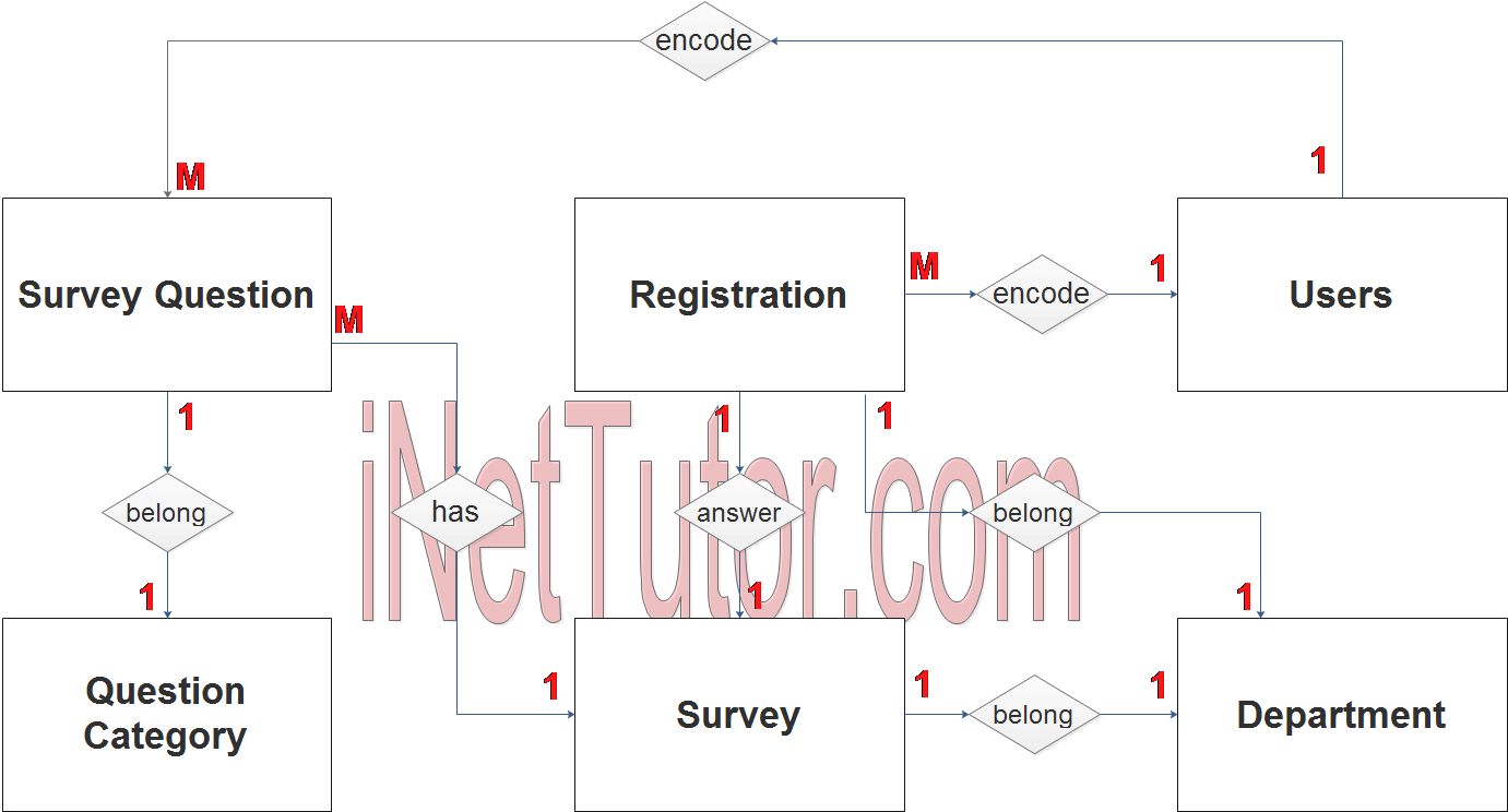
- The user encodes, approves or updates the customer/student information registration (1 to many relationship).
- The customer/student belongs to a certain type or department (1 to 1 relationship).
- The user encodes the questions (1 to many relationship).
- Question belongs to a certain category (1 to 1 relationship).
- Survey has/contains multiple questions (1 to many relationship).
- Survey will be answered and rated by a customer/student (1 to 1 relationship).
- Survey belongs to a specific department or category (1 to 1 relationship).
Step 3. The last part of the ERD process is to add attributes to our entities.
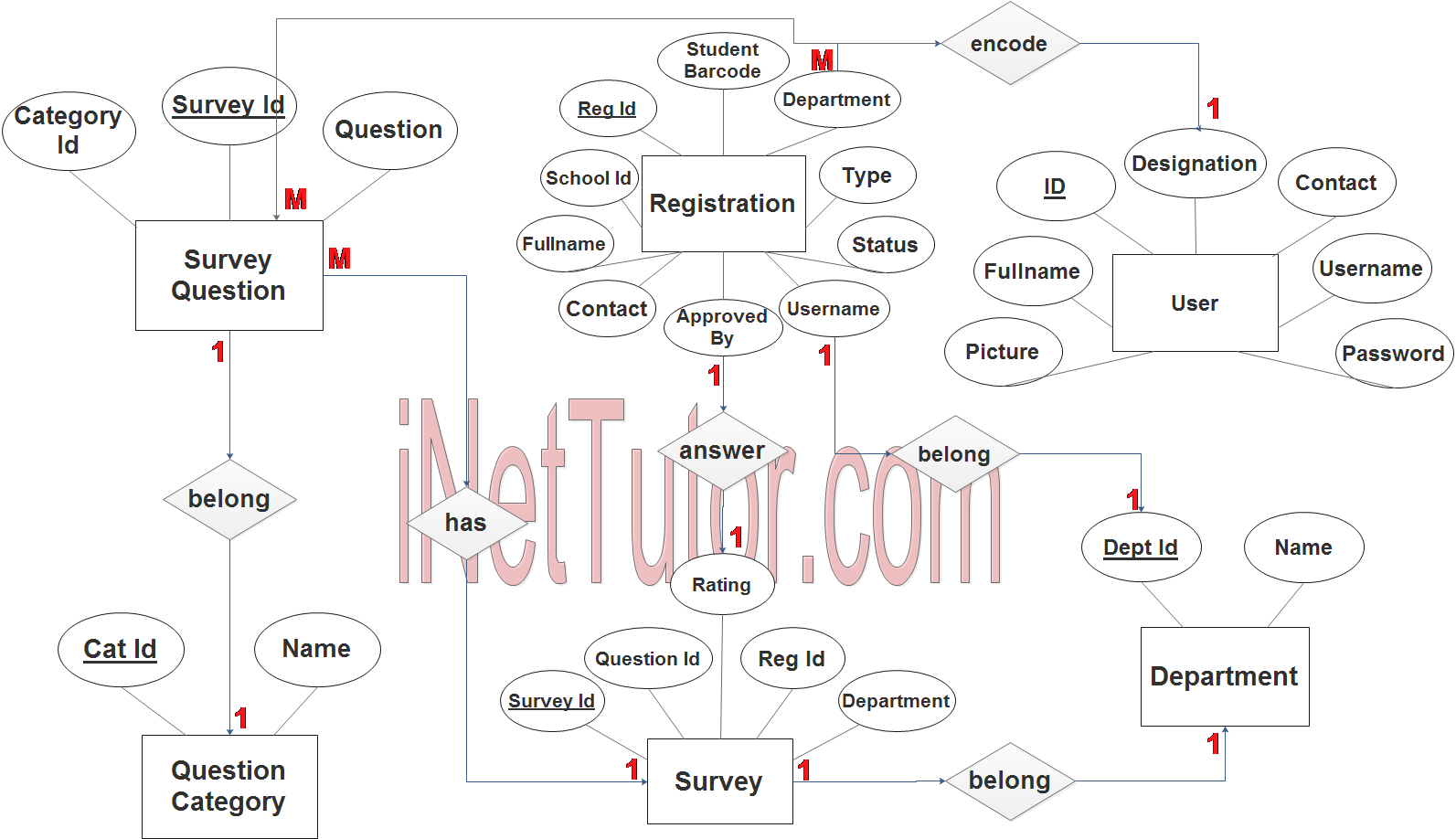
Survey Question Entity has the following attributes:
- Survey ID – primary key represented with underline
- Category ID – foreign key
- Question
Question Category Entity has the following attributes:
- Cat ID – primary key represented with underline
- Name
Survey Entity has the following attributes:
- Survey ID – primary key represented with underline
- Question ID – foreign key
- Reg ID – foreign key
- Department – foreign key
- Rating
Registration Entity has the following attributes:
- Reg ID – primary key represented with underline
- Student ID
- Student Barcode
- Full name
- Contact
- Type
- Status
- Username
- Password
- Approved By – foreign key
Department Entity has the following attributes:
- Dept ID – primary key represented with underline
- Name
User Entity has the following attributes:
- ID – primary key represented with underline
- Full name
- Designation
- Contact
- Picture
- Username
- Password
Note: all attributes with underline represents the primary key of the entity or table.
The next step is to convert the plan designed on ER Diagram into the actual database, please search for the Customer Satisfaction System article which was already posted.
Contact us on our facebook page for the softcopy of the Customer Satisfaction System.
You may visit our facebook page for more information, inquiries and comments.
Hire our team to do the project.