Crime Reporting System ER Diagram
This article will discuss the step by step process on how to prepare the entity relationship diagram or ERD of the project entitled Crime Reporting System.
The objective of the project entitled Crime Reporting System is to provide an avenue for the residents and police to report and respond to crimes reported through this platform. The project was designed and developed in PHP, MySQL and Bootstrap. For more information about the project, you may visit the database design and screen layout of crime reporting system, just search for crime reporting database design and crime reporting user interface.
The first step in the development of the Crime Reporting System is to prepare the ER diagram that will serve as the basis later on in the creation of the actual database.
We will create and explain the process of making the entity relationship diagram of crime reporting system.
Let’s start from the symbols used in the ER Diagram.
Entity is represented by the rectangle shape. The entity will be our database table of Crime Reporting System later on.
Attribute is represented by the oval shape. This will be the columns or fields of each table in the Crime Reporting System.
Relationship is represented by diamond shape. This will determine the relationships among entities. This is usually in a form of primary key to foreign key connection.
We will follow the 3 basic rules in creating the ER Diagram.
- Identify all the entities.
- Identify the relationship between entities and
- Add meaningful attributes to our entities.
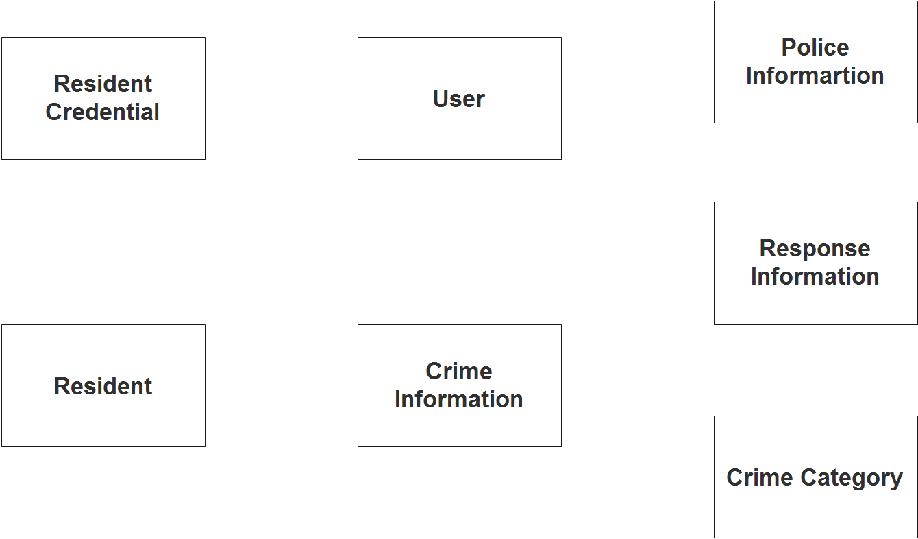
Step 1. In the Crime Reporting System we have the following entities
- User
- Resident
- Resident Credential
- Crime Information
- Crime Category
- Police Information
- Response Information
We will now draw the entities of the Crime Reporting System specified above and it will be represented by a rectangle shape.
Step 2. After we have specified our entities, it is time now to connect or establish a relationship among the entities.
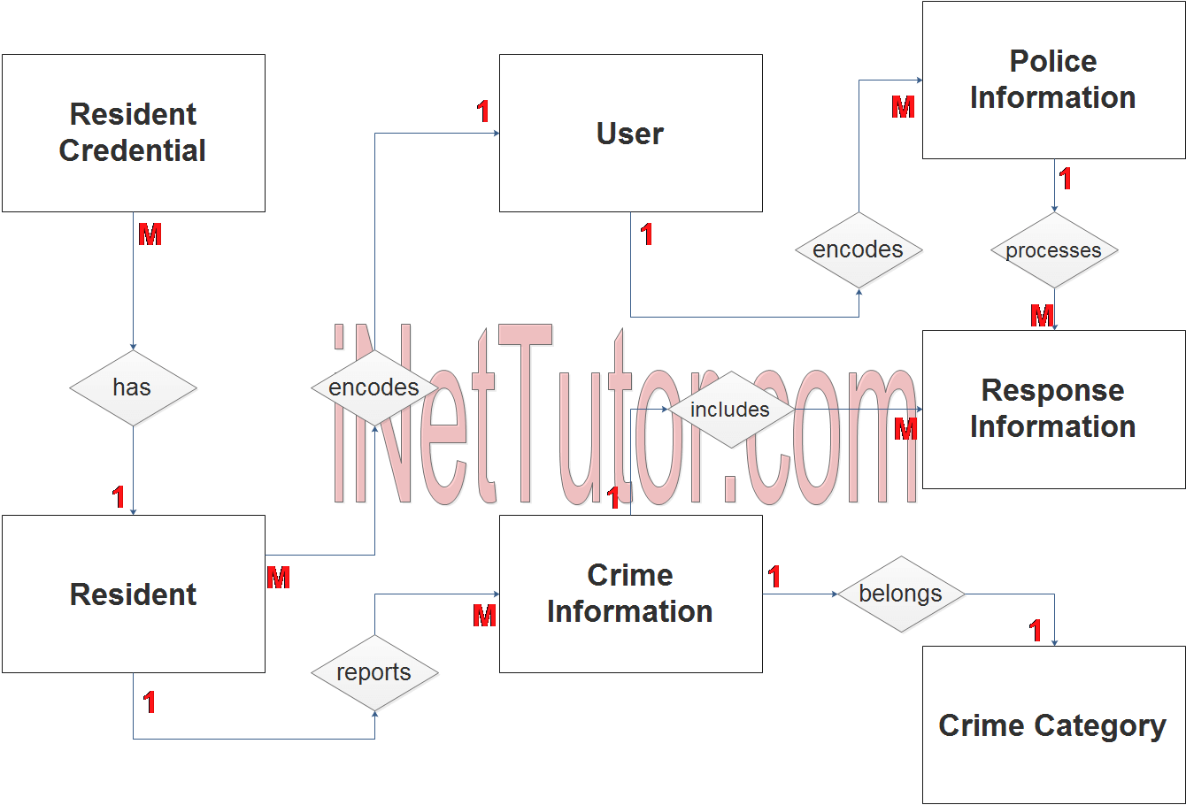
- User encodes information of residents (1 to many relationship).
- A resident uploads or submits their resident credentials (1 to many relationship).
- A resident reports a crime through the online and mobile application of the project (1 to many relationship).
- User encodes information of police officer (1 to many relationship).
- The police officer responds to the crimes reported by the residents (1 to many relationship).
- The crime belongs to a specific crime category (1 to 1 relationship).
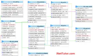
Step 3. The last part of the ERD process is to add attributes to our entities.
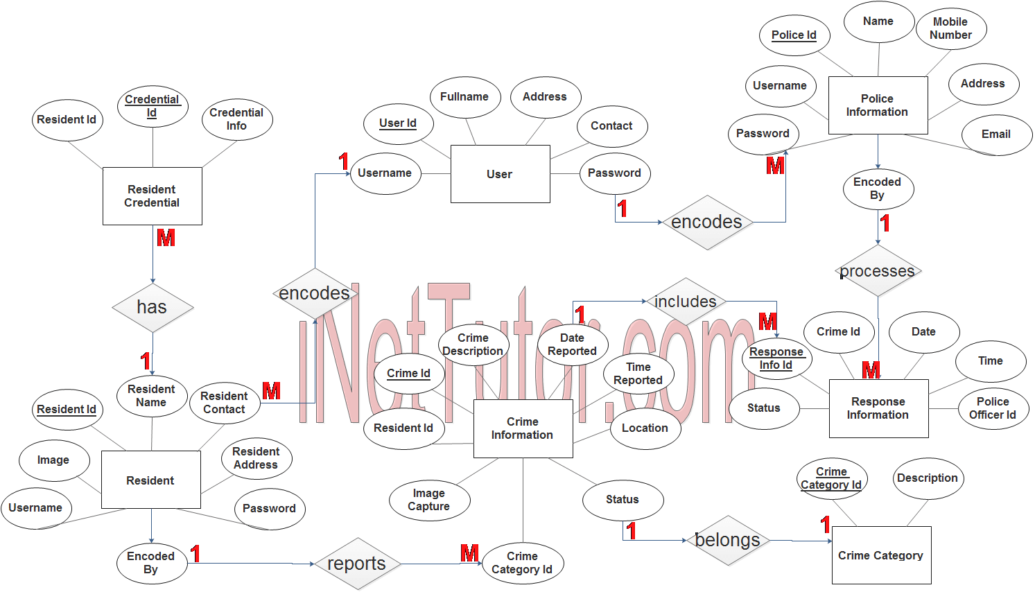
User Entity has the following attributes:
- User ID – primary key represented with underline
- Full name
- Address
- Contact
- Username
- Password
Resident Entity has the following attributes:
- Resident ID – primary key represented with underline
- Resident Name
- Resident contact
- Resident address
- Image
- Username
- Password
- Encoded By – foreign key
Resident Credential Entity has the following attributes:
- Credential ID – primary key represented with underline
- Resident ID – foreign key
- Credential Info
Crime Information Entity has the following attributes:
- Crime ID – primary key represented with underline
- Crime Description
- Resident ID – foreign key
- Date Reported
- Time Reported
- Location
- Image Capture
- Status
Crime Category Entity has the following attributes:
- Crime Category ID – primary key represented with underline
- Description
Police Information Entity has the following attributes:
- Police ID – primary key represented with underline
- Name
- Mobile Number
- Address
- Username
- Password
- Encoded by – foreign key
Response Information Entity has the following attributes:
- Response Info ID – primary key represented with underline
- Crime ID – foreign key
- Status
- Date
- Time
- Police Officer ID – foreign key
Note: all attributes with underline represents the primary key of the entity or table.
The next step is to convert the plan designed on ER Diagram into the actual database, please search for the Crime Reporting System article which was already posted.
Contact us on our facebook page for the softcopy of the Crime Reporting System.
You may visit our facebook page for more information, inquiries and comments.
Hire our team to do the project.