Bus Booking System ER Diagram
The capstone project entitled Bus Booking System is an alternative option to traditional booking system, the output of this project is to automate the manual process of reserving a bus ticket through the online platform. The said system is a web/online portal that allows the customers to view and reserve a seat with the use of their computers and mobile devices. The interface was designed to be responsive which makes it a mobile friendly web application.
This article will discuss the step by step process on how to prepare the entity relationship diagram or ERD of the project entitled Bus Booking System.
The first step in the development of the Bus Booking System is to prepare the ER diagram that will serve as the basis later on in the creation of the actual database.
We will create and explain the process of making the entity relationship diagram of Bus Booking System.
Let’s start from the symbols used in the ER Diagram.
Entity is represented by the rectangle shape. The entity will be our database table of Bus Booking System later on.
Attribute is represented by the oval shape. This will be the columns or fields of each table in the Bus Booking System.
Relationship is represented by diamond shape. This will determine the relationships among entities. This is usually in a form of primary key to foreign key connection.
We will follow the 3 basic rules in creating the ER Diagram.
- Identify all the entities.
- Identify the relationship between entities and
- Add meaningful attributes to our entities.
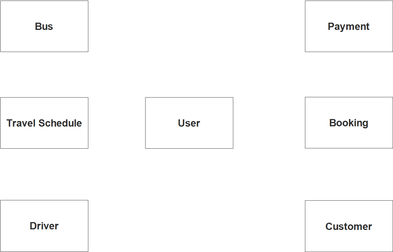
Step 1. In the Bus Booking System we have the following entities
- User
- Bus
- Travel Schedule
- Driver
- Booking
- Payment
- Customer
Our design of Bus Booking System consists of 7 entities; the specified entities will be our database tables in the design and implementation of Bus Booking database schema.
We will now draw the entities of the Bus Booking System specified above and it will be represented by a rectangle shape. The image below is the entities identified in the scope of the Bus Booking System.
Step 2. After we have specified our entities, it is time now to connect or establish a relationship among the entities.
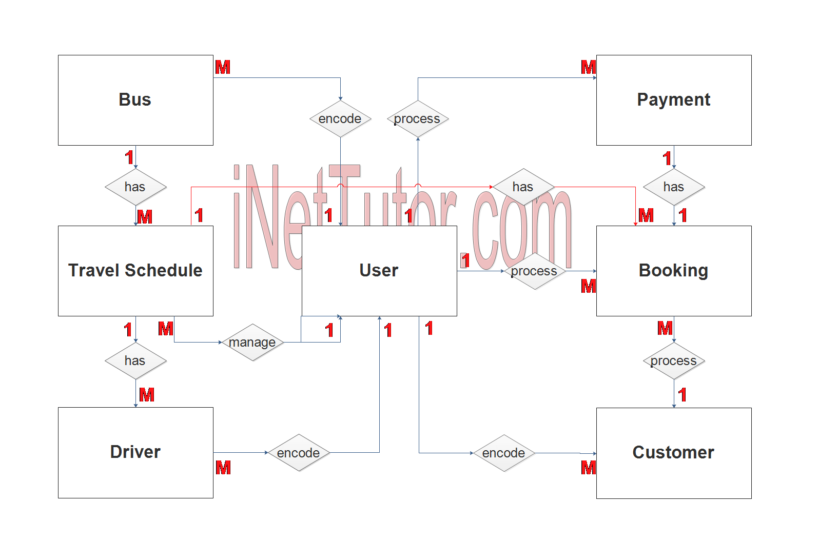
- The user encode/manage/update the bus information (1 to many relationship).
- The bus has schedule of trips/travel (1 to many relationship).
- The user encode/manage/update the travel schedule of buses (1 to many relationship).
- Travel schedule has booking transactions (1 to many relationship).
- Booking of the travel will be managed by the user (1 to many relationship).
- The user encode/manage/update the customer information (1 to many relationship).
- Customer processes and transacts booking of travel (1 to many relationship).
- Booking will be paid by the customer (1 to 1 relationship).
- Payment transactions will be managed by the user The user encode/manage/update the bus information (1 to many relationship).
- The user encode/manage/update the driver information (1 to many relationship).
- The driver has schedule of trips/travel (1 to many relationship).
Step 3. The last part of the ERD process is to add attributes to our entities.
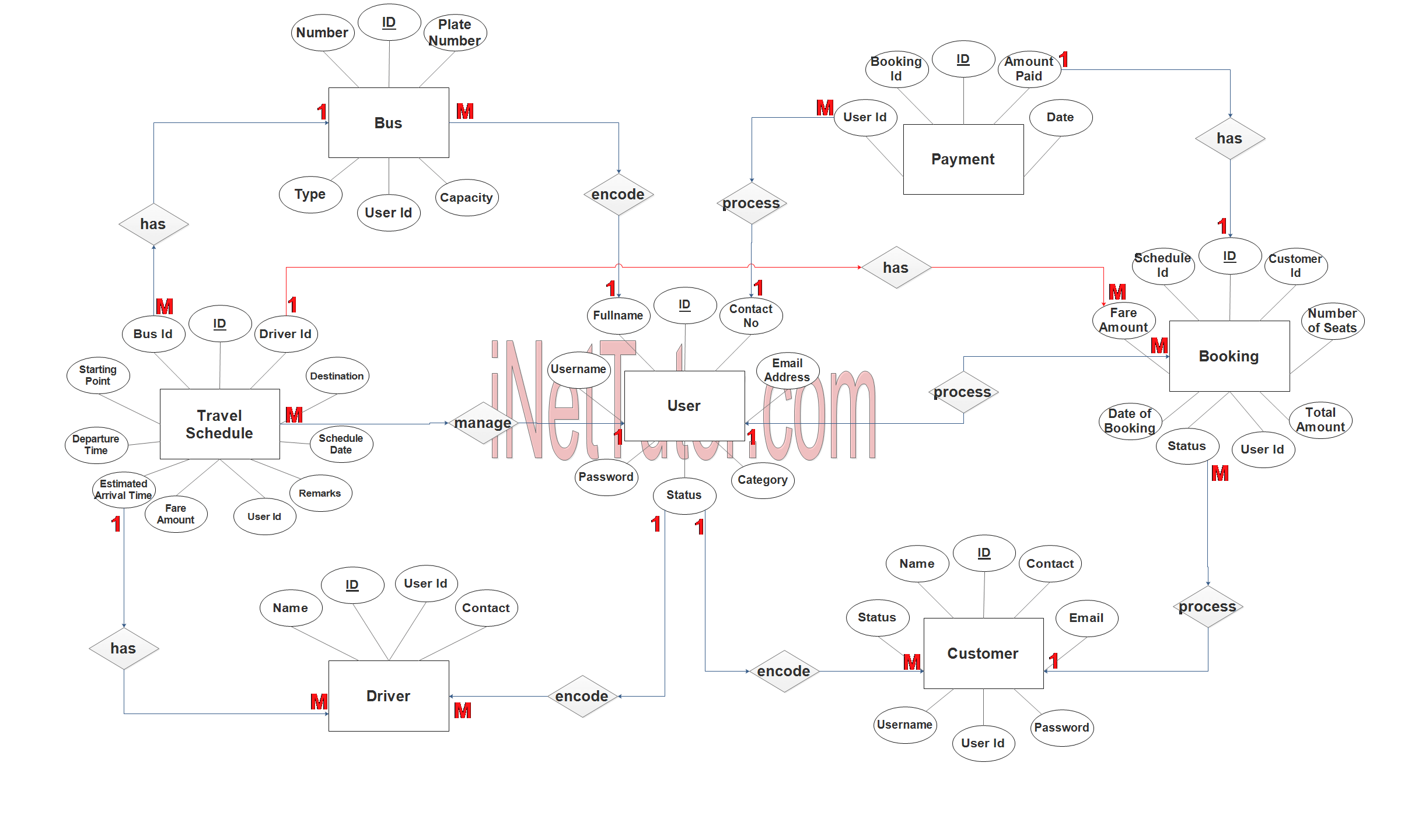
User Entity has the following attributes:
- ID – primary key represented with underline
- Fullname
- Contact
- Email address
- Username
- Password
- Category
- Status
Bus Entity has the following attributes:
- ID – primary key represented with underline
- Number
- Plate Number
- Type
- Capacity
- User ID – foreign key
Travel Schedule Entity has the following attributes:
- ID – primary key represented with underline
- Driver ID – foreign key
- Bus ID – foreign key
- Starting Point
- Destination
- Departure Time
- Estimated Arrival Time
- Schedule Date
- Fare Amount
- Remarks
- User ID – foreign key
Driver Entity has the following attributes:
- ID – primary key represented with underline
- Name
- Contact
- User ID – foreign key
Booking Entity has the following attributes:
- ID – primary key represented with underline
- Customer ID – foreign key
- Schedule ID – foreign key
- Number of Seats
- Fare Amount
- Date of Booking
- Total Amount
- Status
- User ID – foreign key
Payment Entity has the following attributes:
- ID – primary key represented with underline
- Booking ID – foreign key
- Amount Paid
- Date
- User ID – foreign key
Customer Entity has the following attributes:
- ID – primary key represented with underline
- Name
- Contact
- Status
- Username
- Password
- User ID – foreign key
Note: all attributes with underline represents the primary key of the entity or table.
The next step is to convert the plan designed on ER Diagram into the actual database, please search for the Bus Booking System article which was already posted.
Contact us on our facebook page for the softcopy of the Bus Booking System.
You may visit our facebook page for more information, inquiries and comments.
Hire our team to do the project.