QR Fare Payment System Use Case Diagram
QR code technology has revolutionized the way we pay for services, and transportation is no exception. With the advent of QR fare payment systems, riders no longer need to fumble for cash or search for exact change to pay for their transit fares. Instead, they can simply scan a QR code and be on their way. The implementation of QR fare payment systems has numerous benefits, including increased efficiency and improved passenger experience. However, the development of such systems requires meticulous planning and research. One of the essential tools in this process is a use case diagram, which helps identify the different actors, functionalities, and interactions within the system. In this blog post, we will delve deeper into the use case diagram for a QR fare payment system and explore its significance in the development of this technology.
About the Project
Table of Contents
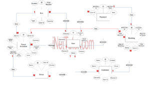
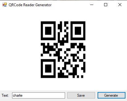
The capstone project, “QR Code Fare Payment System” is designed to automate the procedure of paying for a fare when riding a vehicle. Passengers will register in the system to receive their own QR code, which they will use to pay for their fares by scanning in the system’s QR code scanning page. The project will enable cashless fare payment. The proposed system will eliminate the need of paying in cash when riding a public utility vehicle. The passengers can electronically pay for their fares by using the system. The users will only register to the system to have their own QR code. The QR code will contain their information as well as their balances that they can use to pay for fares. When riding in a public utility vehicle, the users can log in to the system and scan their QR code on the QR scanning page to process their payment easily, quickly, and conveniently. The QR code fare payment system will improve the customer service and experience in riding public utility vehicles.
What is Use Case Diagram?
A use case diagram is a visual representation of the interactions between a system and its users or external systems, outlining the system’s functionalities and use cases. In the research and software development of the QR fare payment system, a use case diagram is crucial in identifying the different actors involved in the system and how they interact with the system. This helps developers to design and implement a system that meets the specific needs of the users and stakeholders. The use case diagram also helps in identifying the various use cases and scenarios involved in the system, which helps in testing and validating the system’s functionality. Additionally, the use case diagram provides a comprehensive view of the system and its interactions, which helps in the development of the system’s architecture and design. Overall, the use case diagram plays a vital role in the development of the QR fare payment system, ensuring that the system meets the needs of its users and stakeholders.
Use Case Diagram
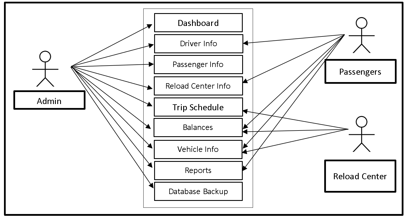
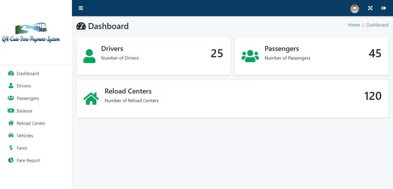
Displayed above is the Use Case Diagram of the capstone project, QR Fare Payment System. The system has three different users, the admin, passengers and reload center. The admin can access the entire core modules of the system. The passengers can access the Driver Info, Reload Center Info, Balances, Vehicle Info and Reports while the Reload Center can access the Trip Schedule, Balances, and Vehicle Info.
Symbols in Use Case Diagram
Use case diagrams use symbols to represent different elements in the system being developed. Here are the commonly used symbols in a use case diagram:
- Actor: An actor is an external user or system that interacts with the system being developed. Actors are represented by stick figures.
- Use Case: A use case represents a specific functionality or task that the system performs to achieve a specific goal. Use cases are represented by ovals.
- Association: An association represents a relationship between an actor and a use case. It shows that an actor is associated with a specific use case. Associations are represented by a straight line.
- System Boundary: A system boundary is a box that encloses all the use cases of the system. It represents the scope of the system being developed.
- Include: An include relationship represents a use case that includes another use case. It is used when a use case needs the functionality of another use case to complete its task.
- Extend: An extend relationship represents a use case that extends another use case. It is used when a use case can add optional functionality to another use case.
- Generalization: A generalization relationship represents a parent-child relationship between use cases. It is used when a child use case inherits functionality from a parent use case.
These symbols help developers to communicate with stakeholders and to model the system being developed in a visual and easy-to-understand way.
Use Cases
The following are the discussions that describe how a user uses a system to accomplish a particular goal.
Use Case: Dashboard
Actor(s): Admin
Description:
This feature is used to manage the information displayed in the dashboard of the QR Code Fare Payment System.
Successful Completion:
- The admin can search, add, update and remove information to be displayed in the dashboard.
Alternative: The admin can access and manage all dashboard information.
Precondition: The admin will login first to access the dashboard.
Post Condition: updated dashboard information.
Use Case: Driver Info
Actor(s): Admin and Passengers
Description:
This feature is used to manage the information of the drivers registered in the system.
Successful Completion:
- The passengers can view information of the driver’s in the system.
- Admin can search, add, update and remove a driver’s information using this feature.
Alternative: Passengers can view driver’s information in the system; admin can update information of old drivers.
Precondition: The admin and the passengers will need to login first to access the Driver Info Module.
Post Condition: registered driver and updated driver information
Use Case: Passenger Info
Actor(s): Admin
Description:
This feature is used to manage the information of the passengers registered in the system.
Successful Completion:
- Admin can search, add, update and remove a passenger’s information using this feature.
Alternative: Admin can register new passengers; admin can update information of old passengers.
Precondition: The admin will need to login first to access the Passengers Info Module.
Post Condition: registered passengers and updated passengers information
Use Case: Reload Center Info
Actor(s): Admin and Passengers
Description:
This feature is used to manage the information of the reload centers registered in the system.
Successful Completion:
- The passengers can view information of reload centers.
- Admin can search, add, update and remove a reload center’s information using this feature.
Alternative: Passengers can view information of reload centers in the system; admin can update information of old reload centers.
Precondition: The admin and the passengers will need to login first to access the Reload Center Info Module.
Post Condition: registered reload center and updated reload center information
Use Case: Trip Schedule
Actor(s): Admin and Reload Center
Description:
This feature is used to view and manage the trip schedules in the system.
Successful Completion:
- The reload centers can view information of the trip schedules in the system.
- Admin can search, add, update and remove a trip schedule’s information using this feature.
Alternative: Reload Center can view information of trip schedules in the system; admin can update information of the trip schedules in the system.
Precondition: The admin and the reload center will need to login first to access the Trip Schedule Module.
Post Condition: updated trip schedule information
Use Case: Balances
Actor(s): Admin, Passengers and Reload Center
Description:
This feature is used to manage balances of passengers and reload centers that can be used for the QR Code Fare Payment.
Successful Completion:
- The passengers and reload centers can view balances.
- The admin can search, add, update and remove balance information in the system.
Alternative: The passengers and reload centers can view balances; the admin can access and manage all balance information.
Precondition: The admin, passengers and reload centers will need to login first to gain access and view balances.
Post Condition: updated balance information.
Use Case: Vehicle Info
Actor(s): Admin, Passengers and Reload Center
Description:
This feature is used to manage vehicle information in the system.
Successful Completion:
- The passengers and reload centers can view information of the vehicles in the system.
- The admin can search, add, update and remove vehicle information in the system.
Alternative: The passengers and reload centers can view vehicle information; the admin can access and manage all vehicle’s information.
Precondition: The admin, passengers and reload centers will need to login first to gain access to Vehicle Info Module.
Post Condition: updated vehicle information
Use Case: Reports
Actor(s): Admin
Description:
This feature is used to view and print the reports such as income and expense, driver commission, trip schedule report in the system.
Successful Completion:
- Admin can view, print and export the report of the system.
Alternative: None
Precondition:
- Admin will need to login to access the reports.
Post Condition: hard and soft copy of the income and expense, driver commission, trip schedule report of the system.
Use Case: Database Backup
Actor(s): Admin
Description:
This feature is used to manage the backup database of the system.
Successful Completion:
- The admin can add, edit, and update database backup information.
Alternative: None
Precondition: Admin will create and connect the backup database.
Post Condition: new backup database.
Summary
The QR Fare Payment System Use Case Diagram is a visual representation of the system’s functionalities and interactions between the users and the system. The diagram illustrates the various use cases that are involved in the QR fare payment system, such as scanning the QR code, processing the payment, and generating a receipt. It also shows the actors or users involved in the system, including the passengers, ticket inspectors, and the system administrator. The blog post explains the purpose of the diagram, which is to provide a clear understanding of the system’s requirements, functionalities, and interactions before the actual development of the system. The article further discusses the benefits of using a use case diagram in the development process, including reducing errors, improving communication between stakeholders, and enhancing the overall quality of the system. Overall, the blog post provides valuable insights into the use of use case diagrams in the development of the QR fare payment system.
Readers are also interested in:
QR Code Attendance System Use Case Diagram
Online Tracking and Monitoring System of Cargo using QR Code
You may visit our Facebook page for more information, inquiries, and comments. Please subscribe also to our YouTube Channel to receive free capstone projects resources and computer programming tutorials.
Hire our team to do the project