Evacuation Center Management System ER Diagram
This article will discuss the step by step process on how to prepare the entity relationship diagram or ERD of the project entitled Evacuation Center Management System.
About the Project
Table of Contents
The capstone project, entitled “Evacuation Center Management System” is designed to automate the management processes of evacuation centers. The said system will assist the local government disaster risk reduction personnel in managing evacuees and their needs. The evacuation center staff can electronically conduct all sorts of recordings plus an inventory of supplies for the evacuees.
An online evacuation center management system is a tool that helps emergency management agencies and organizations to effectively manage and coordinate the operations of evacuation centers during a disaster or emergency situation. It provides a centralized platform for tracking and managing the logistics of evacuating people from an affected area and providing them with temporary shelter, food, and other necessities.
Here are some key features and functionality that an online evacuation center management system might include:
Registration and tracking of evacuees: The system allows evacuees to register themselves and their families at an evacuation center, and tracks their location and status throughout the evacuation process.
Resource management: The system helps emergency management agencies to track and manage the availability and distribution of resources such as food, water, medical supplies, and other necessities at evacuation centers.
Communication and coordination: The system provides a platform for emergency management agencies to communicate with evacuees, volunteers, and other stakeholders involved in the evacuation process. It also enables the coordination of activities such as transportation, medical assistance, and other services.
Reporting and analysis: The system generates reports and analytics on key metrics such as the number of evacuees, the distribution of resources, and the overall effectiveness of the evacuation process. This information can be used to improve the response to future emergencies.
What is an ER Diagram?
Entity-relationship (ER) diagrams are graphical tools used in software development to represent and model the data structures of a database. They provide a visual representation of the relationships between different entities or concepts in the database, and are used to help design and plan the overall structure of the database.
The main purpose of an ER diagram is to provide a clear and concise overview of the data requirements for a system, and to facilitate communication between database designers, developers, and stakeholders. ER diagrams are used to model the data requirements of a system, including the entities that make up the system, the attributes or properties of those entities, and the relationships between the entities.
Let’s start from the symbols used in the ER Diagram.
Entity is represented by the rectangle shape. The entity will be our database table of Evacuation Center Management System later on.
Attribute is represented by the oval shape. This will be the columns or fields of each table in the Evacuation Center Management System.
Relationship is represented by diamond shape. This will determine the relationships among entities. This is usually in a form of primary key to foreign key connection.
We will follow the 3 basic rules in creating the ER Diagram.
- Identify all the entities.
- Identify the relationship between entities and
- Add meaningful attributes to our entities.
Step 1 – Identify the Entities
In the Evacuation Center Management System we have the following entities:
- Evacuation center
- Evacuee information
- LGU
- Barangay
- Calamity
- User
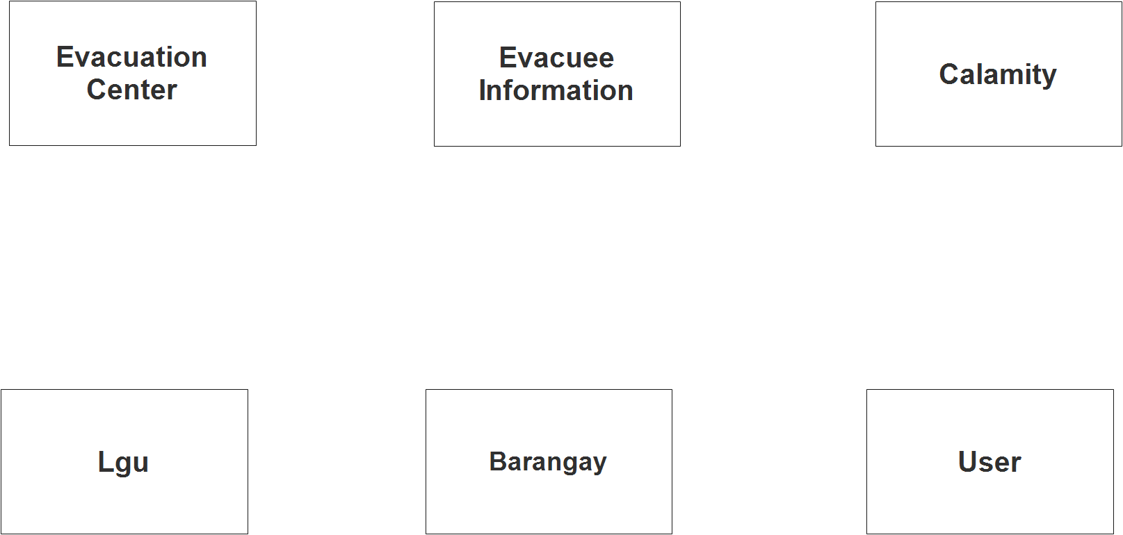
We will now draw the entities of the Evacuation Center Management System specified above and it will be represented by a rectangle shape. The image below are the entities identified in the scope of the Evacuation Center Management System.
Step 2 – Establish the Relationships
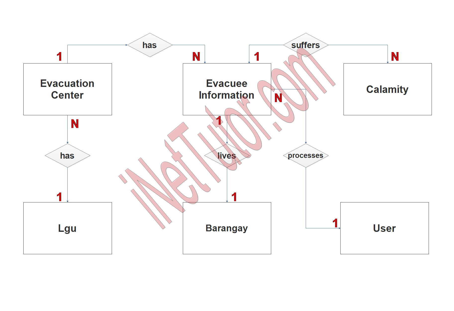
After we have specified our entities, it is time now to connect or establish a relationship among the entities.
- lgu_id has tbl_evacuation_center.lgu_id (1:N). This relationship indicates that each local government unit (LGU) can have multiple evacuation centers, but each evacuation center is associated with only one LGU. This is a one-to-many (1:N) relationship, where tbl_lgu.lgu_id is the primary key and tbl_evacuation_center.lgu_id is the foreign key.
- center.id has tbl_evacuee_information.evacuation.center_id (1:N). This relationship indicates that each evacuation center can have multiple evacuees, but each evacuee is associated with only one evacuation center. This is also a one-to-many (1:N) relationship, where tbl_evacuation_center.center.id is the primary key and tbl_evacuee_information.evacuation.center_id is the foreign key.
- brgy.id lives tbl_barangay.barangay.id (1:1). This relationship indicates that each evacuee lives in only one barangay, and each barangay has only one evacuee. This is a one-to-one (1:1) relationship, where tbl_evacuee_information.brgy.id is the foreign key and tbl_barangay.barangay.id is the primary key.
- calamity.id suffers tbl_calamity.calamity_id (1:N). This relationship indicates that each evacuee may suffer from calamity and each calamity can affect multiple evacuees. This is also a one-to-many (1:N) relationship, where tbl_evacuee_information.calamity.id is the foreign key and tbl_calamity.calamity_id is the primary key.
- user.id processes tbl_evacuee_information.evacuee.id (1:N). This relationship indicates that each user can process the information of multiple evacuees, but each evacuee’s information is processed by only one user. This is also a one-to-many (1:N) relationship, where tbl_user.user.id is the primary key and tbl_evacuee_information.evacuee.id is the foreign key.
Step 3 – Add Meaningful Attributes
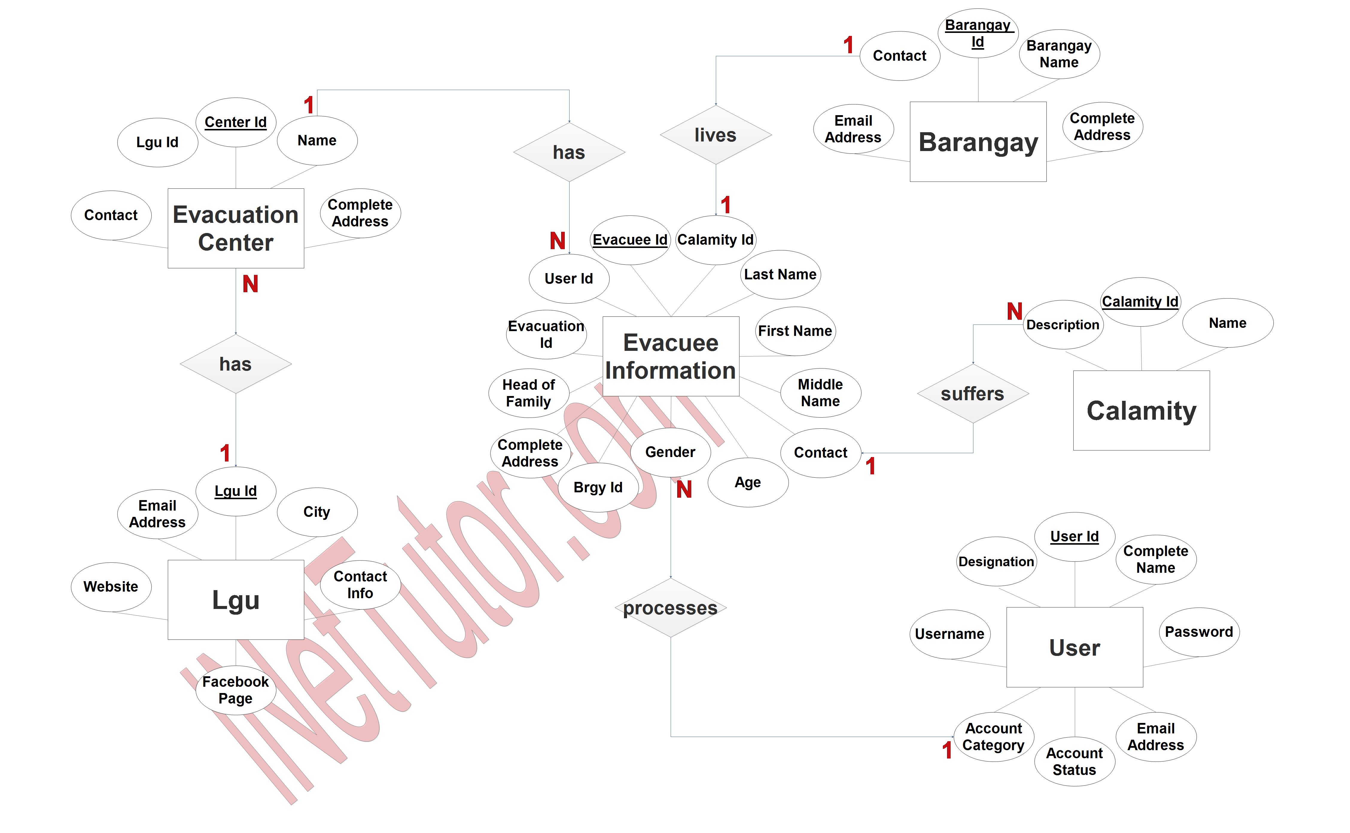
The last part of the ERD process is to add attributes to our entities.
Evacuation center entity has the following attributes:
- Center ID- primary key
- Name
- Complete address
- Contact
- LGU ID – foreign key
Evacuee information entity has the following attributes:
- Evacuee ID – primary key
- Last name
- First name
- Middle name
- Contact
- Age
- Gender
- Brgy ID – foreign key
- Complete address
- Head of family
- Evacuation center ID – foreign key
- Calamity ID – foreign key
- User ID – foreign key
LGU entity has the following attributes:
- Lgu ID – primary key
- City
- Contact info
- Email address
- Website
- Facebook page
Barangay entity has the following attributes:
- Barangay ID – primary key
- Barangay name
- Complete address
- Contact
- Email address
Calamity entity has the following attributes:
- Calamity ID – primary key
- Name
- Description
User entity has the following attributes:
- User ID – primary key
- Username
- Password
- Complete name
- Designation
- Account category
- Email address
- Account status
Note: all attributes with underline represents the primary key of the entity or table.
Summary
Overall, an online evacuation center management system helps to streamline and optimize the process of managing and coordinating evacuation centers during a disaster, enabling emergency management agencies to more effectively protect and support affected communities. ER diagrams are a valuable tool in the software development process, and are used to help design and plan the data structures of a database in a clear and concise way.
The next step is to convert the plan designed on ER Diagram into the actual database, please search for the Evacuation Center Management System article which was already posted.
Readers are also interested in:
Evacuation Center Management System Database Design
Evacuation Center Management System
50+ Free Download Web Based System Template in Bootstrap
You may visit our Facebook page for more information, inquiries, and comments. Please subscribe also to our YouTube Channel to receive free capstone projects resources and computer programming tutorials.
Hire our team to do the project.